


FM
/
AM
Cassette Car
Stereo
Sony Corporation
1998
Printed in Japan
Installation/Connections
XR-C8200
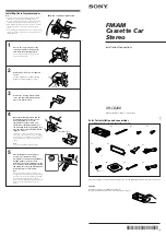
Parts for installation and connections
The numbers in the list are keyed to those in the instructions.
1
2
3
4
5
6
×
4
7
8
The release key
7
is used for dismounting the unit. See the Operating Instructions manual for details.
TOP
*I-3-862-511-11*
(2)
9
(
‘
K3
×
12)
!º
!¡
1
Mark two positions for the supplied
screws.
Use the screw holes on the mounting
hardware
!º
to mark the positions.
!º
2
Choose the exact location for the
rotary commander to be mounted,
then clean the mounting surface.
Dirt or oil impair the adhesive strength of the
double-sided adhesive tape.
Installing the rotary commander
Example of a mounting location
Notes
• Choose the mounting location carefully so that the rotary
commander will not interfere with operating the car.
• Do not install the rotary commander in a place where it may
jeopardize the safety of the (front) passenger in anyway.
• When installing the rotary commander, be sure not to damage
the electrical cables etc. on the other side of the mounting
surface.
• Avoid installing the rotary commander where it may be subject
to high temperatures, such as from direct sunlight or hot air
from the heater etc.
Marks
Remove the steering wheel column
cover, and drill 2 mm diameter holes
where you have marked.
3
4
Warm the mounting surface and the
double-sided adhesive tape on the
mounting hardware
!º
to the
temperature of 20°C to 30°C, and
attach the mounting hardware onto
the mounting surface by applying even
pressure. Then screw it down with the
supplied screws
9
.
Attach a piece of heavy duty tape etc. on the other
side of the mounting surface to cover the protruding
tips of the screws so that they will not interfere with
the electrical cables etc. inside the steering wheel
column.
Note
Cut the mounting hardware
!º
if necessary.
Heavy duty tape etc.
!º
9
After installing the steering wheel
column cover, attach the rotary
commander to the mounting hardware
by aligning the four holes on the
bottom of the rotary commander to the
four catches on the mounting hardware
and sliding the rotary commander until
it locks into place as illustrated.
Note
If you are mounting the rotary commander to the
steering wheel column, make sure that the protruding
tips of the screws on the inner surface of the column
do not in anyway hinder or interfere with the
movement of the rotating shaft, operative parts of the
switches or the electrical cables etc. inside the
column.
5
Holes
!™
Caution
Cautionary notice for handling the bracket
1
.
Handle the bracket carefully to avoid injuring your fingers.
TOP


