


Advanced Operations for Shooting
88
Ch
apt
er 4
S
hoo
tin
g
Setting the title prefix
You can assign title prefixes by choosing from a
prefix list stored in internal memory, or by
entering the prefix directly.
However, to choose from a prefix list, you must
create the list beforehand on a computer and
transfer it to the unit's internal memory with a
“Memory Stick”.
Setting the initial value of the serial number
The initial value of the serial number can be set to
00001 (the default) or to any other number. The
number is automatically incremented by 1 each
time you record a clip. When it reaches 99999, it
returns to 00001 for the next clip.
Note
Duplicate clip titles can be generated depending on the
serial number setting, for example if you reset the serial
number to the original value after recording several clips.
Care should be taken when setting the serial number.
To assign user-defined titles
automatically when clips are recorded
(How to select an item in the menu screen: Turn
the MENU knob to move
b
to the desired item.)
1
Display the CLIP TITLE page of the
OPERATION menu.
For details on menu operations, see “Basic
menu operations” on page 163.
2
Select “TITLE” and then press the
MENU knob.
3
Turn the MENU knob to display
“ENABL” and then press the MENU
knob.
Clip titles will be generated automatically if
you record in this state.
The title of the next clip to be recorded will
be a combination of the prefix in the PREFIX
field and the serial number in the NUMERIC
field.
To create a list of title prefix strings
Prepare the data beforehand according to the
following rules.
File name
Assign the name “TITLES.TXT” to the file.
Input format
Enter title prefixes one at time, separated by
newline (CRLF) characters.
Prefixes can be up to 10 characters long. A prefix
file can contain up to 20 prefixes.
Allowable characters
•
Digits:
0 to 9
•
Alphabetic characters:
a to z, A to Z
• The following symbols:!, #, $, %, &, ', ( , ), ~, =,
-, ^, @, [, ], {, }, +, ; (semicolon), , (comma), .
(period), _ (underscore)
• Space
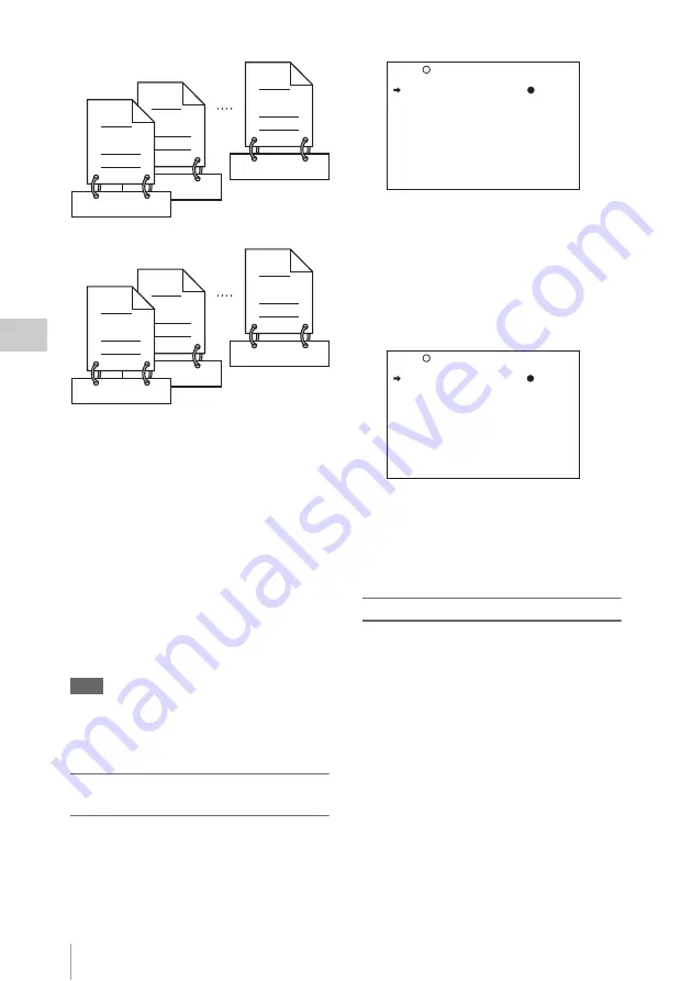
C0020.MXF
TITLE00020
C0002.MXF
TITLE00020
C0017.MXF
TITLE00037
C0002.MXF
TITLE00022
TITLE00001
C0001.MXF
TITLE00021
C0001.MXF
Clips recorded on Disc 1
Clips recorded on Disc 2
TITLE : DSABL
027 CLIP TITLE TOP
TITLE : ENABL
SELECT PREFIX : EXEC
CLEAR NUMERIC : EXEC
LOAD PREFIX DATA: EXEC
PREFIX : TITLE
NUMERIC : 00001
027 CLIP TITLE TOP


