


1-3
WRR-862A/862B
5
(GB)
C
GP/CH (group/channel) indication
Shows the receiving channel group and channel number.
Each time you press the MODE button the group/channel
indication changes to the frequency, squelch level,
accumulated time of battery use and backlight mode
indications.
For each item setting, see “Settings" from page 7 to 12.
D
RF (radio frequency) indications
The number of dots shows the RF input level as below.
Four dots on:
more than 35 dB
µ
Three dots on:
between 25 dB
µ
and 35 dB
µ
Two dots on:
between 15 dB
µ
and 25 dB
µ
One dot on:
between 5 dB
µ
and 15 dB
µ
No dot:
less than 5 dB
µ
signal reception stand-by mode. Set to OFF to search outside
noise or a radio wave which may disrupt the transmission.
Note
If you turn off the SQUELCH switch when the tuner is in
stand-by condition for signal receiving or when the RF input
level is low, noise may be heard or the connected device or
speakers may be damaged. Be sure to operate this switch
only after minimizing the input of the connected device.
See “Setting the Squelch Level” on page 10.
9
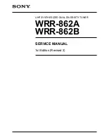
Display section
Shows the status of the tuner; the left display shows the
tuner 1, and the right shows the tuner 2.
For details of each indication, see
A
to
D
.
A
AF (audio frequency) indication
Lights when the output audio signal is over the reference
level.
B
BATT (battery) indication
Displays the status of the batteries of this tuner.
See “Battery indication” on page 6.
Group/channel
Frequency
Squelch level
Accumulated time
of battery use
Group/channel and frequency indications show those of
the U66 model as an example
Backlight mode
GP
AF
RF
BATT
CH
GP
AF
RF
BATT
CH
A
B
C
D
6
(GB)
Power Supply
Installing the batteries
The tuner can operate on four LR6 (size AA) alkaline
batteries continuously for about 5 hours at 25
°
C (77
°
F).
1
Slide the battery-holder catches inward to take out the
battery holder.
2
Match the polarities and insert the batteries.
3
Set the battery holder in the original position.
Confirm that both catches on the holder are locked.
Battery indication
When you turn the power on, the battery status of this unit
appears in the BATT indication on the display section.
Note
The indication may be incorrect if the batteries are not new
when installed. If you plan to use the tuner for a long
period, it is best to replace the batteries with new ones.
0
+ (+ selection) / – (– selection/reset) buttons
When setting the transmission channel, frequency, squelch
level and backlight mode, press these buttons to change its
contents. The “–” button resets the accumulated time
indication to “00:00”.
qa
SET button
Press to set and fix the item on the display.
qs
MODE button
Press to select the item shown on the display.
qd
CONTROL switch
Select the tuner to be set.
qf
POWER switch
Turns the power of the tuner ON or OFF.
qg
DC 12V IN connector
For external power operation, connect to an external power
supply (DC 10 V to 17 V) of a camcorder using the supplied
power cable.
For connecting the antennas, output cables and DC power
cable and attaching the unit to a camcorder, see
“Appendix” on page 15.
Four Alkaline batteries LR6 (sizeAA)
Parts Identification
7
(GB)
Notes on batteries
•
Use new alkaline batteries.
•
Do not use different types of batteries together.
•
Always replace the four batteries together.
•
The batteries are not rechargeable.
•
Be careful to install the batteries with the correct polarity.
•
When not using the tuner for a long period, remove the
batteries to avoid leakage. If the batteries do leak, clean all
leakage from the battery holder case and the unit. Leakage
left in the holder case and the unit may cause poor battery
contact. If there seems to be poor battery contact, consult
your Sony dealer.
External power operation
To operate on an external power supply (DC 10 V to 17 V),
connect the DC 12V IN connector to the DC OUT connector
of a camcorder using the power cable supplied. When the
external power is supplied, the tuner functions regardless of
the built-in batteries.
3
4,6,8
5,7
2
1
OFF
GP
AF
RF
BATT
CH
GP
AF
RF
BATT
CH
ON
1+2
A
TX BATT
B
RF
1
2
OFF
ON
CONTROL
SQUELCH
MONITOR
POWER
2
1
MODE
SET
A
B
RF
Settings
To set the tuner in Setting Mode, press the SET button. The
indication on the display starts to flash waiting for you to
press the +/– buttons to change the contents on the display.
The Setting Mode is automatically cancelled if no buttons
are pressed for 30 seconds while the indication flashes.
Wireless Channel Selection
Note
Noise may occur when the power is turned on or off. Be
sure to turn down the input level of the connected equipment
before operating the POWER switch.
Good
1
2
3
4
BATT
indication
Lights
Lights
Lights
Less than
50% charge
BATT
condition
Flashes
Less than
20% charge
Almost
exhausted
8
(GB)
Settings
1
Set the POWER switch to ON.
The display shows the same status as before the tuner
was last turned off.
2
Set the CONTROL switch to “1” or “2”.
The tuner to be set is selected.
If the group name and channel number is shown on the
display, skip step
3
and proceed with step
4
.
3
Press the MODE button until the group and channel
number appear on the display.
4
Press the SET button.
The group indication starts flashing.
5
Press the + or – button to select the desired group.
Pressing the + button cyclically changes the group in the
following order. Pressing the – button changes it in the
reverse order.
If you hold the button down, the group will continuously
change.
Group setting
Display example for U66 model
Model available in USA
Model available in Europe (CE21)
Model available in Australia
Содержание WRR-862A
Страница 1: ...UHF SYNTHESIZED DUAL DIVERSITY TUNER WRR 862A WRR 862B SERVICE MANUAL 1st Edition Revised 2 ...
Страница 10: ......
Страница 72: ......
Страница 75: ...7 3 WRR 862A 862B 7 3 RX 60 RX 60 RX 60 A SIDE SUFFIX 11 RX 60 B SIDE SUFFIX 11 ...
Страница 77: ...7 5 WRR 862A 862B 7 5 AU 276 B SIDE SUFFIX 11 AU 276 A SIDE SUFFIX 11 AU 276 AU 276 ...
Страница 79: ...8 1 WRR 862A 862B 8 1 Section 8 Schematic Diagrams ...
Страница 85: ......
Страница 95: ......
Страница 96: ...Printed in Japan Sony Corporation 2006 6 22 2001 WRR 862A AU WRR 862B U CE E 9 976 896 03 ...