


1-2
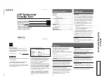
WRR-802A (U)
3
US
Frequency band
Model name
TV channel
Transmitter or
microphone
Frequency
(MHz)
Tuner
64
770.125 to
775.875
WRT-805A (64)
WRT-807A (64)
WRT-808A (64)
WRT-810A (64)
WRT-820A (64)
WRT-822A (64)
WRT-860A (64)
WRR-802A (64)
WRR-805A (64)
MB-806A with
WRU-806A (64)
WRR-810A (64)
WRR-820A (64)
WRR-840A (64)
WRR-850A (64)
WRR-855A (64)
65
776.125 to
781.875
66
782.125 to
787.875
WRT-805A (66)
WRT-807A (66)
WRT-808A (66)
WRT-810A (66)
WRT-820A (66)
WRT-822A (66)
WRT-860A (66)
WRR-802A (66)
WRR-805A (66)
MB-806A with
WRU-806A (66)
WRR-810A (66)
WRR-820A (66)
WRR-840A (66)
WRR-850A (66)
WRR-855A (66)
67
788.125 to
793.875
68
794.125 to
799.875
WRT-805A (68)
WRT-807A (68)
WRT-808A (68)
WRT-810A (68)
WRT-820A (68)
WRT-822A (68)
WRT-830A (68)
WRT-860A (68)
WRT-867A (68)
WRR-802A (68)
WRR-805A (68)
MB-806A with
WRU-806A (68)
WRR-810A (68)
WRR-820A (68)
WRR-840A (68)
WRR-850A (68)
WRR-855A (68)
WRR-860A (68)
69
800.125 to
805.875
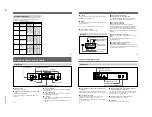
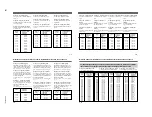
System Configuration
The unit can be used with a Sony UHF synthesized wireless
microphone or UHF synthesized transmitter among the
models listed in the table below.
Sony 800 MHz-band system models
4
US
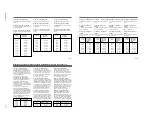
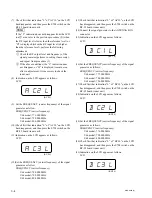
Front Panel
1
POWER switch
2
ANTENNA A, B connectors
3
GP button
4
CH button
5
+ button
7
Display
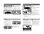
1
POWER switch
Turns the power on and off.
2
ANTENNA A, B (antenna A, B) connectors (BNC
type)
Connect the supplied antennas.
The DC power voltage is not output from the antenna
connector.
3
GP (group) button
To change the group, press the + or – button while holding
this button down.
4
CH (channel) button
To change the channel in a group, press the + or – button
while holding this button down.
5
+ button
To go to a higher group or channel, press this button while
holding the GP or CH button.
Press this button changes the indication from GP/CH to
frequency.
Location of Parts and Controls
ON
ANTENNA A
VOL.
ANTENNA B
OFF
POWER
MIN
MAX
CH
GP
+
–
GP
CH
BATT
AF
RF
6
– button
8
VOL. Control
5
US
4
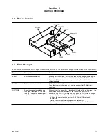
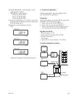
BATT indication
1
AF indicator
2
AF level indications
3
BATT indicator
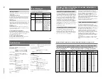
1
AF (audio frequency) indicator
2
AF (audio frequency) level indications
The indicator lights and the indications appear when the
audio output level is higher than the reference level.
3
BATT (battery) indicator
4
BATT (battery) indication
Indicate the condition of the wireless microphone
transmitter batteries. The indicator and indication appear
and start flashing about one hour before the transmitter
batteries go flat. The time at which flashing begins will
depend on the type of battery used in the transmitter, and its
condition.
5
GP/CH (group/channel) indication
Shows the reception channel group and respective channel
number.
Pressing the + button changes this indication to the
frequency indication.
6
RF (radio frequency) level indications
7
RF (radio frequency) indicator
The indicator lights and the indications (dots) appear when
the antenna reception is optimal. Depending on the RF input
level, the number of dots changes.
6
– button
To go to a lower group or channel, press this button while
holding the GP or CH button.
7
Display
Displays the status of the tuner and the group and channel
assigned to the unit.
For details, see the following section “Display”.
8
VOL. (volume) control
Adjusts the volume of the tuner output.
Display
GP
CH
BATT
AF
RF
7
RF indicator
6
RF level indications
5
GP/CH indication
6
US
TUNER OUTPUT
LINE LEVEL –20dBm
TRS PHONE BALANCED
LEVEL
LINE
MIC
–58dBm
–20dBm
DC IN 9V
¥
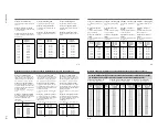
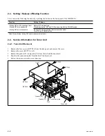
Rear Panel
1
TUNER OUTPUT connector
3
TUNER OUTPUT connector
1
TUNER OUTPUT (tuner sound output) connector
(XLR type)
Supplies audio signals. You can connect this to the audio
input connector of a mixer, amplifier, or similar equipment.
2
OUTPUT LEVEL switch
Select the output level of the XLR-type connector as
–20 dBm or –58 dBm. (0 dBm = 0.775 Vrms)
Set this switch according to the input level of the equipment
connected to the tuner.
2
OUTPUT LEVEL switch
Location of Parts and Controls
3
TUNER OUTPUT (tuner sound output) connector
(ø6.3 phone balanced (
1
/
4
inch TRS))
Supplies audio signals. You can connect this to the audio
input connector of a mixer, amplifier, or similar equipment.
The output level is fixed at –20 dBm.
4
DC IN 9V (9 V DC power input) connector
Connect the supplied AC power adaptor.
5
Cord clamp
Attaches the cord of the AC power adaptor.
4
DC IN 9V connector
5
Cord clamp