background image

14

Channel Setting

The CH indication shows the lowest frequency channel
of the selected group. For group 00, however, the
channel selected last is displayed.
Releasing the buttons automatically cancels the group
selection mode, and the currently displayed group is
selected.

4

While holding down the SET button, press the CH
button to select a channel.

Similar to step 

3

, each time you press the CH button,

the CH indication changes in the order shown in the
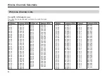
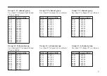
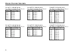
group and reception channel list. (See “Wireless
Channel Lists” on page 6.)
If you press the CH button when the last channel of the
selected group is displayed, the first channel of the
group will be displayed.

Selecting the reception channel by frequency
Press the GP button.

This changes the GP/CH indication to a frequency
indication.

GP

CH

GP

CH

Note

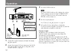
Turn the POWER switch on after reducing the volume
of equipment connected to the TUNER OUTPUT
connector. Otherwise, noise will be heard when the
power is turned on.

2

Press the SET button and hold it down.

The unit changes to the group and channel selection
mode.

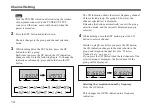
3

While holding down the SET button, press the GP
button to select a group.
Each time you press the GP button, the GP indication
changes as shown in the following figure. To change the
indication continuously, press and hold down the GP
button.

GP

CH

GP

CH

Содержание WRR-800A

Страница 1: ...3 860 929 31 1 Operating Instructions WRR 800A 1997 by Sony Corporation AU UHF Synthesized DiversityTuner ...

Страница 2: ...n of the signal to noise ratio do not use the unit in noisy places or in locations subject to vibration such as the following near electrical equipment such as motors transformers or dimmers near air conditioning equipment or places subject to direct air flow from an air conditioner near public address loudspeakers where adjacent equipment might knock against the unit Switching lights on or off ma...

Страница 3: ... designed to enable simultaneous use of multiple channels when channels are selected according to the Sony channel plan Features Phase Locked Loop PLL synthesized system The WRR 800A has a refined phase locked loop PLL synthesizer circuit and covers two UHF TV channels It operates on 102 channels over a 14 MHz frequency Preprogrammed wireless channel plan for simultaneous multichannel operation Th...

Страница 4: ...ndby mode Compander system A compander compressor expander system enables stabilized wireless transmission over a wide dynamic range Overview System Configuration The unit can be used with a Sony UHF synthesized wireless microphone or UHF synthesized transmitter among the models listed in the table below Sony 800 MHz band system models Frequency band Model name TV channel Transmitter or microphone...

Страница 5: ...digit number for example 66 23 Note To eliminate interference or noise please note the following Do not use two or more wireless microphones or transmitters whose wireless channels are the same If there is a TV broadcasting station nearby to avoid possible interference from its broadcasting do not use that station s channel The number of wireless microphone channels actually usable in a multi chan...

Страница 6: ...67 45 804 750 67 46 804 875 67 47 805 000 67 48 805 125 67 49 805 250 67 50 805 375 67 51 805 500 WL Channel Frequency MHz WL Channel Frequency MHz Channel Frequency MHz Channel Frequency MHz 67 01 799 250 67 02 799 375 67 03 799 500 67 04 799 625 67 05 799 750 67 06 799 875 67 07 800 000 67 08 800 125 67 09 800 250 67 10 800 375 67 11 800 500 67 12 800 625 67 13 800 750 67 14 800 875 67 15 801 00...

Страница 7: ... 500 67 08 800 125 67 19 801 500 67 33 803 250 67 39 804 000 67 42 804 375 67 46 804 875 Group 12 9 channel group Use when TV channel 66 is on the air WL Channel Frequency MHz 67 01 799 250 67 03 799 500 67 11 800 500 67 16 801 125 67 23 802 000 67 27 802 500 67 41 804 250 67 44 804 625 67 50 805 375 Group 13 9 channel group Use when TV channel 67 is on the air WL Channel Frequency MHz 66 01 792 2...

Страница 8: ...93 875 66 18 794 375 66 21 794 750 WL Channel Frequency MHz 66 02 792 375 66 04 792 625 66 10 793 375 66 15 794 000 66 19 794 500 66 22 794 875 WL Channel Frequency MHz 66 31 796 000 66 33 796 250 66 39 797 000 66 44 797 625 66 48 798 125 66 51 795 500 WL Channel Frequency MHz 66 32 796 125 66 34 796 375 66 40 797 125 66 45 797 750 66 49 798 250 WL Channel Frequency MHz 67 03 799 500 67 05 799 750...

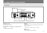
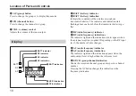
Страница 9: ...ton 7 VOL Control 6 CH button 1 POWER switch Turns the power on and off 2 ANTENNA A B antenna A B connectors BNC type Connect the supplied antennas 3 Display Displays the status of this unit and the groups and channels assigned to the unit For details see the following section Display 4 SET button Press to change the group or channel Location of Parts and Controls ...

Страница 10: ...the transmitter batteries go flat 2 RF radio frequency indicator 7 RF radio frequency indications The indicator lights and the indications dots appear when the antenna reception is optimal Depending on the RF input level the number of dots changes 3 AF audio frequency indicator 4 AF audio frequency indication The indicator lights and the indication appears when the audio output level is higher tha...

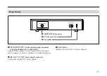
Страница 11: ...output connector ø6 3 phone balanced 1 4 inch TRS Supplies audio signals You can connect this to the audio input connector of a mixer amplifier or similar equipment 2 DC IN 9V 9 V DC power input connector Connect the supplied AC power adaptor 3 Cord clamp Attaches the cord of the AC power adaptor 2 DC IN 9V connector ...

Страница 12: ... the wireless microphone or transmitter Use the wireless microphone or transmitter to which the same channel is assigned as to this unit If noise is heard Depending on the environment where the system is installed outside noise or radio wave may disrupt the transmission of certain channels To select a channel under this circumstance turn off the wireless microphone or transmitter Then select a cha...

Страница 13: ...e unit receives an interference RF signal 3 Noise squelch The audio output is muted to eliminate noise which may be heard when there is such excessive interference RF signal that the tone squelch does not work Channel Setting Take the following precautions to prevent interference and noise Do not simultaneously use two or more microphones and transmitters that are set to the same channel When simu...

Страница 14: ...the last channel of the selected group is displayed the first channel of the group will be displayed Selecting the reception channel by frequency Press the GP button This changes the GP CH indication to a frequency indication GP CH GP CH Note Turn the POWER switch on after reducing the volume of equipment connected to the TUNER OUTPUT connector Otherwise noise will be heard when the power is turne...

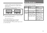
Страница 15: ... for 5 seconds The group and channel set in the procedure explained above are stored in memory GP CH GP CH Error Messages Meaning Remedy Err 01 Message An error has occurred in the backup memory data The memory data is initialized Reset the group and channel settings Contact your nearest Sony dealer The PLL synthesized circuit has a malfunction Err 02 NO TONE As no tone signal is available or a to...

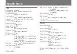
Страница 16: ...z deviation at 1 kHz modulation Distortion 1 or less 40 kHz deviation at 1 kHz modulation Tone signal frequency 32 768 kHz Output level 0 dBm2 16 kHz deviation at 1 kHz modulation 20 dBm 5 kHz deviation at 1 kHz modulation Output impedance 150 ohms Output connector ø6 3 phone balanced 1 4 inch TRS 1 0 dBµ 1 µV 2 0 dBm 0 775 Vrms 600 ohms loaded General Power requirements 9 V DC Current consumption...

Отзывы: