background image


62

Replacing the Lamp 
and Cleaning the 
Ventilation Holes 
(intake)

The lamp used for the light source has a 
certain lifespan. When the lamp dims, the 
color balance of the picture becomes strange, 
or “Please replace the Lamp.” appears on the 
screen, the lamp may be exhausted. Replace 
the lamp with a new one (not supplied) 

without delay.

Tools you need to get started:
• Projector Lamp LMP-H330 (Optional)
• Standard Phillips screwdriver
• Cloth (for scratch protection)

• The lamp remains hot after the unit is turned 

off with the 

?

/

1

 (ON/STANDBY) button. If 

you touch the lamp, you may burn your 
fingers. When you replace the lamp, wait for 
at least 1 hour for the lamp to cool.

• Do not touch the surface of the lens. If you 

touch it, wipe off the fingerprints with a soft 
cloth.

• Pay special attention to replacing the lamp 

when the unit is installed on the ceiling.

• When replacing the lamp of a unit which is 

on the ceiling, do not stand  directly under the 
lamp cover. When removing the lamp door 
(inner cover), avoid twisting it.
If the lamp explodes, fragments may cause 
injury.

• When removing the lamp unit, make sure it 

remains horizontal, then pull straight up. Do 
not tilt the lamp unit. If you pull out the lamp 
unit while tilted and if the lamp breaks, the 
pieces may scatter, causing injury.

1

Turn off the unit and unplug the 
AC power cord.

2

When setting the unit on a flat 
surface such as a desk etc., put 
a cloth to prevent the surface 
from being scratched. Place the 
unit on the cloth.

Be sure that the unit is placed on a stable 
surface.

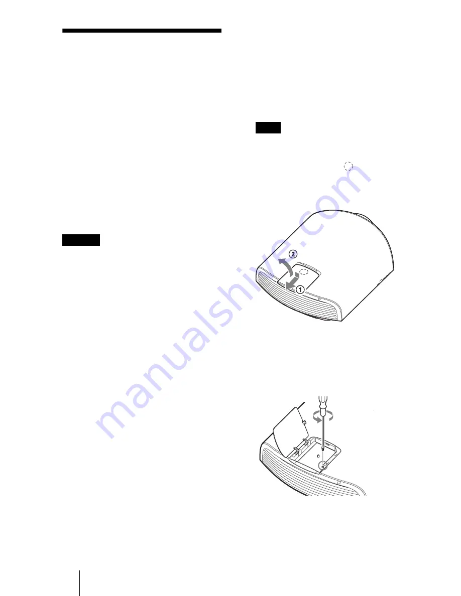
3

While pressing the 

 part 

indicated in the lamp cover 
illustration, slide 

1

 and then 

open 

2

 the lamp cover.

4

Loosen the lamp door (inner 
cover) screw with a Phillips 
screwdriver, and then open the 
lamp door.

Caution

Note

Содержание VPLGT100

Страница 1: ...ng Instructions Before operating the unit please read this manual and supplied Quick Reference Manual thoroughly and retain it for future reference VPL GT100 4 456 405 11 1 Data Projector 2012 Sony Corporation ...

Страница 2: ...g the Picture Position 25 Selecting the Aspect Ratio According to the Video Signal 26 Selecting the Picture Viewing Mode 29 Using ImageDirector3 to Adjust the Picture Quality 30 Operation through the Menus 31 Picture Menu 33 Screen Menu 38 Setup Menu 40 Function Menu 42 Installation Menu 45 Information Menu 49 About the Preset Memory No 49 Using Network Features 50 Displaying the Control Window of...

Страница 3: ...nge 77 Dimensions 81 Index 84 Others Trademark Information PS3 is a registered trademark of Sony Computer Entertainment Inc The terms HDMI and HDMI High Definition Multimedia Interface and the HDMI Logo are trademarks or registered trademarks of HDMI Licensing LLC in the United States and other countries Blu ray and Blu ray Disc are trademarks of Blu ray Disc Association DisplayPort DisplayPort lo...

Страница 4: ...VER indicator 1 page 60 M m arrow enter button 1 page 31 DisplayPort 1 2 connector 1 page 16 HDMI connector 1 page 15 REMOTE connector Connects to a computer etc for remote control 1 page 30 TRIGGER 1 TRIGGER 2 connector 1 page 45 While the ON STANDBY indicator lights in orange the power saving mode is on 1 page 41 Note Control panel LENS button 1 page 10 IR IN connector Inputs signals to control ...

Страница 5: ...C IN socket 1 page 7 Projector suspension support attaching hole 1 page 82 Front feet adjustable 1 page 14 Ventilation holes intake Remote control detector 1 page 10 Ventilation holes intake AC inlet cover supplied For details on how to attach the AC inlet cover see page 7 ...

Страница 6: ...GHT button Illuminates the buttons on the remote control CALIBRATED PRESET buttons 1 page 29 3D button 1 page 23 ASPECT button 1 page 26 POSITION button 1 page 25 SHARPNESS button 1 page 35 MENU button 1 page 31 ADVANCED IRIS button 1 page 34 COLOR TEMP button 1 page 35 REALITY CREATION button 1 page 34 BLACK LEVEL button 1 page 36 GAMMA CORRECTION button 1 page 37 MOTION ENHANCER button 1 page 35...

Страница 7: ... picture etc Connecting the AC Power Cord 1 Plug the AC power cord into the AC IN socket then attach the plug holder to the AC power cord 2 Slide the plug holder over the AC power cord to fix to the unit 3 Attach the AC inlet cover to the unit Preparation Plug holder supplied AC power cord supplied AC IN socket AC inlet cover supplied ...

Страница 8: ...d adjust the picture so that it fits the screen 1 page 10 When using a screen with an uneven surface stripes pattern may rarely appear on the screen depending on the distance between the screen and the unit or the zooming magnifications This is not a malfunction of the unit When installing the unit on the ceiling Do not mount the projector on the ceiling or move it by yourself Be sure to consult w...

Страница 9: ... is a possibility of spoiling the performance of the unit significantly depending on the installation position Do not mount the projector on the wall or move it by yourself Be sure to consult with qualified Sony personnel ...

Страница 10: ...ENT FOCUS ZOOM SHIFT buttons of the remote control When adjusting the lens each time you press the LENS button on the unit the lens adjustment function switches between Lens Focus Lens Zoom and Lens Shift Depending on the installation location of the unit you may not control it with the remote control In this case point the remote control at the remote control detector of the unit or the screen No...

Страница 11: ...t adjust the focus the picture size or the proper position by pressing the FOCUS ZOOM or SHIFT buttons 1 page 45 When Test Pattern is set to Off on the Function menu the test pattern is not displayed 1 page 44 Adjust the lens by using buttons on the remote control or the control panel of the unit Never make adjustments by directly turning the lens with your hands which may cause damage or malfunct...

Страница 12: ...just to the proper position of the picture by pressing the M m buttons Tip The test pattern disappears when no operation has been performed for one minute Whenever you press the button the test pattern disappears When adjusting the window position do not touch the lens unit otherwise your fingers may be pinched by the moving parts Note ...

Страница 13: ...icture projected on the screen moves up or down by a maximum of 80 of the screen height from the center of the lens Top view Picture position when moving the picture to the left at maximum Picture position when moving the picture to the right at maximum 31 1 screen width 31 80 1 screen height 80 Side view Picture position when moving the picture upward at maximum Picture position when moving the p...

Страница 14: ...table to keep the unit level If the unit is tilted up or down the projected image may be trapezoidal Be careful not to catch your finger when turning the front feet adjustable Lens adjustment window test pattern Note Notes Range of movement of the projected picture Projected Picture H Width of the projected picture V Height of the projected picture 0 8V 0 8V 0 31H 0 31H Front feet adjustable Turn ...

Страница 15: ...g instructions of the connected equipment To connect to equipment with HDMI output connectors Connect to a Blue ray disc player recorder or PS3 equipped with HDMI output If you have a Control for HDMI compatible equipment you can operate the unit synchronizing with the Control for HDMI compatible equipment For details see HDMI Setting of the Function menu 1 page 43 and About the Control for HDMI 1...

Страница 16: ...heck the settings of the connected equipment When connecting two DisplayPort cables to project a 4096 2160 or 3840 2160 high resolution picture connect DisplayPort output 1 and DisplayPort output 2 of the workstation to DisplayPort input 1 and DisplayPort input 2 of the unit respectively If no picture is projected with the workstation connected to the unit with DisplayPort cables check the setting...

Страница 17: ...ear properly Set your computer to output the signal to only the external monitor For details refer to the computer s operating instructions supplied with your computer For settings of the computer consult with the manufacturer of the computer If the picture from equipment connected to the unit with an HDMI or DisplayPort cable is not correct check the settings of the connected equipment Connecting...

Страница 18: ...mitter Do not connect computers or other network devices to avoid malfunction You can use a 3D Sync Transmitter separate from this unit using an optional LAN cable straight type If the usage environment has interference of a continuous specific frequency synchronization of 3D image signals and the 3D glasses may be lost In this case use a LAN cable labeled Category 7 When watching 3D images in an ...

Страница 19: ... The USB connector of this unit is for output only Do not connect the unit to a USB port of a PC etc it may cause a malfunction Sony is not liable for loss of data or failure of a device arising from a USB connection with the unit Before using read the manual of the device to be connected Before using be sure to check the rated voltage and current of the device For safety if the input current is h...

Страница 20: ...ette When Status is set to Off or All Off on the Setup menu the input palette does not appear Press the INPUT button to switch between input terminals in sequence When the Control for HDMI is set to On on the Function menu the input terminal with effective signals is automatically displayed synchronizing with the operation of the equipment connected to HDMI input of the unit Only when the connecte...

Страница 21: ...TANDBY button for about 1 second instead of performing the above steps Projecting high resolution images V Split display Signals transferred after an image is split at 4096 2160 or 3840 2160 resolution are projected 1 Connect DisplayPort output 1 and DisplayPort output 2 of the workstation to DisplayPort input 1 and DisplayPort input 2 of the unit respectively 1 page 16 2 Turn on the unit and work...

Страница 22: ...structions for the connected equipment 2 Turn on the unit and project the 3D video image onto the screen For details on how to project the image see Projecting the Picture 1 page 20 3 Turn on the 3D glasses and then put them on so that they fit comfortably For details on how to use the 3D glasses see Using the 3D Glasses 1 page 23 Tips The factory default setting for 2D 3D Display Sel is Auto to a...

Страница 23: ...ilt into the front of the unit which are reflected to the glasses from the screen When watching 3D video images using the 3D glasses face squarely toward the screen 1 Press the power button on the 3D glasses The LED indicator lights up in green 2 Put on the 3D glasses 3 Turn toward the screen Precautions for use The 3D glasses receive infrared signals sent by the 3D Sync Transmitter built into the...

Страница 24: ...not be able to display the images properly Also the viable angles and distance vary depending on the screen type environment of the room and installation environment of the unit Figure A 3D sync signal communication distance Shift Range 0 5 V Figure B 3D glasses communication range The figure shows the distance between the screen and the projector as 8 m Screen a Projector Side view 3D glasses b a...

Страница 25: ... 2 35 1 are projected on a 2 35 1 screen After you have selected and confirmed the lens position the lens starts to move Do not touch or place anything near the lens otherwise it may cause injury or a malfunction If you press any button on the unit while the lens is moving the lens stops In this case select the lens position again or adjust the lens manually The Picture Position function is not gu...

Страница 26: ...ited for the video signal received Press ASPECT Each time you press the button you can select the Aspect setting You can also select it using the menu 1 page 39 Original image Recommended setting and resultant images ASPECT button 1 85 1 Squeezed 1 85 1 1 85 1 Zoom 2 35 1 Squeezed 2 35 1 2 35 1 Zoom ...

Страница 27: ...rojecting Adjusting an Image Original image Recommended setting and resultant images 1 78 1 16 9 1 33 1 4 3 1 33 1 4 3 with side panels Normal Squeezed Stretch 2 35 1 V Stretch When using an anamorphic lens ...

Страница 28: ...ode taking into account that changing the aspect ratio of the original picture will provide a different look from that of the original image Note that if the unit is used for profit or for public viewing modifying the original picture by switching the aspect may constitute an infringement of the rights of authors or producers which are legally protected Notes Original image Recommended setting and...

Страница 29: ...ture quality suited to reproducing digital cinema like images resembling DCI specifications 1 page 56 REF A picture quality setup suitable for when you want to reproduce faithfully the original image quality or for enjoying image quality without any adjustment TV Picture quality suited for watching TV programs sports concerts etc PHOTO Ideal for projecting still images taken with a digital camera ...

Страница 30: ...loaded from the Sony website http esupport sony com US p select system pl http www pro sony eu pro article projectors home cinema article When connecting the REMOTE or LAN connector with a computer connect while the power of the computer and the unit is off You cannot adjust the picture quality when Gamma Correction in the Picture menu is set to Off When you set Gamma Correction in the Picture men...

Страница 31: ...he next menu window with setting items appears 1 Press MENU The menu window appears 2 Press M m to select a menu item and press or The items that can be set or adjusted with the selected menu appear The item presently selected is shown in white 3 Press M m to select an item you want to set or adjust and press or The setting items are displayed in a pop up menu in a setting menu in an adjustment me...

Страница 32: ...When the screen display appears select Yes using and press All of the following settings are reset to its factory preset value Reality Creation Cinema Black Pro Motionflow Contrast Brightness Color Hue Color Temp Sharpness and Expert Setting on the Picture menu To reset the items that have been adjusted Select an item in the menu screen and display the pop up menu the setting menu or the adjustmen...

Страница 33: ...ty suited to reproducing digital cinema like images resembling DCI specifications 1 page 56 Reference A picture quality setup suitable for when you want to reproduce faithfully the original image quality or for enjoying image quality without any adjustment TV Picture quality suited for watching TV programs sports concerts etc Photo Ideal for projecting still images taken with a digital camera Game...

Страница 34: ... between the peak light and dark parts expresses a large dynamic range This results in a bright and high contrast image Auto Limited A lower brightness than Auto Full making the image suitable for viewing in a dark room Manual Manually fixed adjusts the iris Off Disables the iris aperture function Lamp Control Switches the lamp output High Increases the brightness and projects brighter images Low ...

Страница 35: ...comes The lower the setting the more reddish the picture becomes Color Temp COLOR TEMP Adjusts the color temperature D93 Equivalent to 9 300 K color temperature normally used in TVs Gives white colors a blue tint D75 Equivalent to 7 500 K color temperature used as an ancillary standard illuminant Gives a neutral tint between D93 and D65 D65 Equivalent to 6 500 K color temperature used as a standar...

Страница 36: ...can adjust the smooth gradation effect Off The smooth gradation function is not applied Film Mode According to the film source you have selected make a setting for playback Auto 1 Suitable for reproducing the original picture movement Normally set this to Auto 1 Auto 2 Reproduces a 2 3 or 2 2 Pull Down format video signal such as film sources in a smooth picture movement When a video signal other ...

Страница 37: ... when playing back an x v Color video signal Set this item to On when connecting the unit with equipment that supports x v Color and playing back an x v Color video signal For details on x v Color see About the x v Color 1 page 56 Tip Setting x v Color to On disables gamma adjustment Color Space COLOR SPACE Converts the color space BT 709 An ITU R BT 709 color space which is used for high definiti...

Страница 38: ...at position it is overwritten Delete Deletes the stored setting After the setting is deleted 1 85 1 2 35 1 Custom 1 Custom 2 or Custom 3 in the display change to Select Recalls the settings of the selected position Tip The optimal aspect ratio is preset for each picture position The aspect ratio can be changed and saved for each picture position After you have selected and confirmed the lens posit...

Страница 39: ...eo with a commercially available anamorphic lens When you select V Stretch from Trigger Select 1 2 on the Installation menu a 12 V signal is output from the TRIGGER 1 or TRIGGER 2 connector 1 page 45 Squeeze With this setting 1 78 1 16 9 and 1 33 1 4 3 video will be displayed in their correct aspect ratios when you use a commercially available anamorphic lens Tips When you select V Stretch or Sque...

Страница 40: ...ng All Off Language Selects the language used in the menu and on screen displays Available languages are English Dutch French Italian German Spanish Portuguese Russian Swedish Norwegian Japanese Chinese Simplified Chinese Chinese Traditional Chinese Korean Thai and Arabic Menu Position You can change the position to display the menu on the screen Bottom Left Displays the menu on the bottom left ar...

Страница 41: ... the PJ Auto Power On function is disabled The function is set to Off and does not appear in the menu The network function is also disabled in standby mode Power Saving Sets the power saving mode Lamp Cutoff If no signal is input for 10 minutes the lamp turns off automatically and power consumption is reduced If signal is resumed or any button on the control panel or remote control is pressed the ...

Страница 42: ... the 3D system of those HDMI signals 2D Displays 2D video images The 3D information is additional information to discriminate 3D Some HDMI signals have additional information to discriminate 3D and some HDMI signals have none 3D Format Set the 3D system when the input HDMI signals do not include 3D information Simulated 3D Converts 2D video images to 3D video images The setting can be made only fo...

Страница 43: ...best viewed with the 3D glasses HDMI Setting You can change the settings of the Control for HDMI function Control for HDMI Selects the function whether to turn the Control for HDMI function effective when the HDMI connector is connected to a Control for HDMI compatible equipment When set to On the following are available The operation of the unit and the connected Control for HDMI compatible equip...

Страница 44: ...set for signals of 16 235 Full The video input level is set for signals of 0 255 If the video output setting of the connected HDMI or DisplayPort device is not set correctly light and dark parts of the video may appear too light or too dark Auto Input Search Enables selection from only the input which has a signal When set to On inputs without signals do not appear on the input palette that appear...

Страница 45: ...amorphic lens with a horizontal rate of 1 24 1 32x Select this when you use an anamorphic lens with a horizontal rate of 1 32 Trigger Select Switches the output function of the TRIGGER 1 TRIGGER 2 connector Off Turns off the TRIGGER connector function Power Outputs 12 V signals from the TRIGGER 1 TRIGGER 2 connectors when the unit is on The TRIGGER 1 TRIGGER 2 connectors do not output any signals ...

Страница 46: ...gion within the four directions of the screen Select the edge to adjust by highlighting Left Right Top or Bottom using the M m buttons Adjust the amount of blanking using the buttons Tip Depending on the aspect ratio setting right left blanking may not be available ...

Страница 47: ...G B White all colors when the Adjust Color is B Blue Adjust The shift adjustment and zone adjustment of the color selected in Adjust Color can be made with M m buttons When Shift is selected Assign the settings of the horizontal direction H with buttons and the vertical direction V with M m buttons on the shift adjustment screen When Zone is selected Select the position to adjust with buttons for ...

Страница 48: ...IP Address Setup select the item with the buttons and input the value with the M m buttons When all items are entered select Apply and then press the button The entered settings will be registered IP Address Set the unit s IP address 1 0 0 0 223 255 255 255 Subnet Mask Set the unit s subnet mask 1 0 0 0 255 255 255 255 Default Gateway Set the unit s default gateway 1 0 0 0 223 255 255 255 Primary ...

Страница 49: ... type of that signal are displayed in the Information menu For information on the preset signals see the table Preset Signals 1 page 68 Depending on the computer input signal parts of screen may be hidden or displayed incorrectly Model name Displays the model name VPL GT100 Serial No Displays the serial number Memory No Displays the preset memory number of the input signal Signal type Displays the...

Страница 50: ...d control protocol Advertisement PJ Talk SNMP AMX DDDP Dynamic Device Discovery Protocol Using the gamma control software ImageDirector3 The menu displays used for the explanation below may be different depending on the model you are using Supported Web browsers are Internet Explorer 6 7 8 9 The menu displays only English If the browser of your computer is set to Use a proxy server when you have a...

Страница 51: ...llowing in the address field then press the Enter key on your computer http xxx xxx xxx xxx xxx xxx xxx xxx IP address for the unit You can confirm the IP address of the unit under Network Setting on the Installation menu The following window appears in the Web browser Once you make the network settings you can open the Control window only by performing step 3 of this procedure LAN cable straightt...

Страница 52: ...en you change the password input a new password after deleting the password that was set If you forget your password consult with qualified Sony personnel You can confirm the current settings for the unit on the Information page You can control the unit from the computer on the Control page The functions of the buttons shown in the operation area are the same as those of the buttons on the supplie...

Страница 53: ...x then check the Report Timing check box of the e mail report to be sent 4 Set the mail account for sending e mail reports Mail Address Enter the e mail address Outgoing Mail Server SMTP Enter the address of outgoing mail server SMTP Required Authentication Check this check box if authentication is required for sending e mail Requires the use of POP Authentication before send email POP before SMTP...

Страница 54: ...mail report When you click on View the contents of the e mail report are displayed 6 Send the test mail Check on the Send test mail check box then click on Apply to send your test mail to the e mail address you set You cannot use the e mail report function because Outbound Port 25 Blocking on the network is preventing a connection to the SMTP server You cannot enter the following characters in the...

Страница 55: ...trol for HDMI Be sure to assign the appropriate settings for both the projector and the Control for HDMI compatible equipment connected to the projector For settings of the projector see page 43 For settings of the Control for HDMI compatible equipment connected to the projector refer to its operating instructions When equipment that is compatible with the Control for HDMI Easy Setting is connecte...

Страница 56: ...em About HDCP HDCP High Bandwidth Digital Content Protection is the copyright protection technology which enciphers the digital signal transmitted and received via a HDMI terminal or a DisplayPort terminal and prevents unauthorized copying As the HDMI input and DisplayPort input of this unit are compliant with HDCP a digital image which is protected by HDCP technology can be projected About the si...

Страница 57: ... c Check that the computer signal is set for output to an external monitor c If the notebook computer etc signal is output to its display and an external monitor the external monitor s image may not be displayed correctly Set your computer to output the signal to only an external monitor The picture has ghosts c Video images are displayed in 3D Watch the 3D video images using the 3D glasses and se...

Страница 58: ... model name does not disappear from the screen c The display mode of the unit may be set at the time of purchase Consult with your local dealer or qualified Sony personnel Input terminals do not appear c Set Auto Input Search on the Function menu to Off 1 page 44 Symptom Cause and Remedy The remote control does not work c Batteries could be weak Replace them with new batteries c Insert the batteri...

Страница 59: ...reen size is not appropriate Set the zooming magnification to low or watch the image from farther away from the screen 1 page 78 Symptom Cause and Remedy The fan is noisy c Check the setting of High Altitude Mode on the Setup menu 1 page 40 c Make sure that the room temperature is not too high c Check the installation conditions 1 page 8 The number of fan rotation increases to maintain the product...

Страница 60: ... be at the end of its service life In this case replace the lamp with a new one 1 page 62 ON STANDBY flashes in red A repetition rate of 4 flashes c The fan is broken Consult with qualified Sony personnel ON STANDBY flashes in red A repetition rate of 2 flashes c The internal temperature is unusually high Check to ensure that if nothing is blocking the ventilation holes or whether or not the unit ...

Страница 61: ... temperature is high High Altitude Mode should be On if projector is being used at high altitude c When using the unit at high altitude set High Altitude Mode to On 1 page 40 c Check to ensure that the ventilation holes on the unit are not covered 1 page 5 Power Saving Mode is set Projector lamp will automatically cutoff in 1 minute c Power Saving is set to Lamp Cutoff 1 page 41 If no signal is in...

Страница 62: ... attention to replacing the lamp when the unit is installed on the ceiling When replacing the lamp of a unit which is on the ceiling do not stand directly under the lamp cover When removing the lamp door inner cover avoid twisting it If the lamp explodes fragments may cause injury When removing the lamp unit make sure it remains horizontal then pull straight up Do not tilt the lamp unit If you pul...

Страница 63: ...e and attach it 6 Push in the new lamp by the handle securely until it reaches the end and then tighten the 3 screws Be careful not to touch the optical block inside the unit 7 Close the lamp door inner cover and then tighten the screw 8 Close the lamp cover 9 Wipe dust off the ventilation holes intake with a soft cloth Note Handle Note Ventilation holes intake ...

Страница 64: ...n If the lamp breaks broken lamp pieces may scatter and cause injury When the unit is on the ceiling remove the lamp door inner cover by sliding it horizontally slowly after raising it with 30 degree opened Avoid twisting the lamp door inner cover Disposal of the used lamp For the customers in the USA Lamp in this product contains mercury Disposal of these materials may be regulated due to environ...

Страница 65: ...ticide Clean the unit with a cleaning cloth Wiping with a dirty cloth may scratch the unit Using such materials or maintaining prolonged contact with rubber or vinyl materials may result in damage to the screen surface and cabinet material Black points and bright points red blue or green on the screen The projector is manufactured using high precision technology You may however see tiny black poin...

Страница 66: ...ax 100 mA REMOTE RS 232C D sub 9 pin female LAN RJ45 10BASE T 100BASE TX IR IN Minijack 3D SYNC RJ45 connector USB USB TYPE A DC 5 0V Max 500 mA General Outside dimensions w h d 520 mm 200 mm 640 mm 20 1 2 7 7 8 25 1 4 inches without protrusions Mass Approx 20 kg 44 lb 1 5 oz Power requirements AC 100 V to 240 V 5 1 A to 2 0 A 50 60 Hz Power consumption 510 W Standby power requirements 3 9 W when ...

Страница 67: ... NOT BE LIABLE FOR DAMAGES OF ANY KIND INCLUDING BUT NOT LIMITED TO COMPENSATION OR REIMBURSEMENT ON ACCOUNT OF THE LOSS OF PRESENT OR PROSPECTIVE PROFITS DUE TO FAILURE OF THIS UNIT EITHER DURING THE WARRANTY PERIOD OR AFTER EXPIRATION OF THE WARRANTY OR FOR ANY OTHER REASON WHATSOEVER The United States Canada Continental Europe UK Ireland Australia New Zealand Japan China Plug type YP 3 YP 12A Y...

Страница 68: ... 1080 60p 1920 1080p 67 500 60 000 13 1080 50p 1080 50p 1920 1080p 56 260 50 000 14 1080 24p 1080 24p 1920 1080p 26 973 23 976 18 720 60p Frame packing 720 60p 1280 720p 90 000 60 000 19 720 50p Frame packing 720 50p 1280 720p 75 000 50 000 20 1080 24p Frame packing 1080 24p 1920 1080p 53 946 23 976 26 640 480 VESA 60 31 469 59 940 32 800 600 VESA 60 37 879 60 317 37 1024 768 VESA 60 48 363 60 004...

Страница 69: ... Video GBR signal Signal Preset memory number Component signal HDMI connector 5 to 8 10 to 14 18 to 20 93 to 96 Component signal DisplayPort 1 2 connectors 5 to 8 10 to 14 74 1 76 1 93 to 96 Video GBR signal HDMI connector 5 to 8 10 to 14 18 to 20 93 to 96 Video GBR signal DisplayPort 1 2 connectors 5 to 8 10 to 14 74 1 76 1 93 to 96 Computer signal HDMI connector 10 to 13 2 26 32 37 45 47 50 55 C...

Страница 70: ...o 96 Contrast z z z Brightness z z z Color z z Hue z z Color Temp z z z Sharpness z z NR z excluding preset memory numbers 74 76 and 93 to 96 z excluding preset memory numbers 74 76 and 93 to 96 MPEG NR z excluding preset memory numbers 74 76 and 93 to 96 z excluding preset memory numbers 74 76 and 93 to 96 Smooth Gradation z excluding preset memory numbers 74 76 and 93 to 96 z excluding preset me...

Страница 71: ...ems that are adjustable can be set Color Correction z z z Clear White z z z x v Color z Color Space z z z Item Input signal Component signal Video GBR signal Computer signal Item Input signal Component signal Video GBR signal Computer signal Aspect 1 z excluding preset memory number 76 and 96 z excluding preset memory number 76 and 96 Over Scan z excluding preset memory numbers 74 76 and 93 to 96 ...

Страница 72: ... 3D Signals Resolution 3D signal format 720 60 50p Side by Side format Over Under format Frame packing 1080 60 50i Side by Side format 1080 24p Over Under format Frame packing 1080 60 50p Side by Side format Over Under format 3D Signals and Adjustable Setting Items Item 3D signals 720 60 50p 1080 60 50i 1080 24p 1080 60 50p Reality Creation z z z z Advanced Iris Lamp Control z z z z Film Projectio...

Страница 73: ... For further details refer to the tables in Aspect Mode 1 page 73 Selectable items vary depending on the type of input signal or 3D format For details see the tables below Items that cannot be selected are not displayed in the menu Item 3D format Over Under Side by Side Simulated 3D Reality Creation z z z Advanced Iris Lamp Control z z z Film Projection Motion Enhancer z preset memory number 14 on...

Страница 74: ... to 95 7 8 10 to 14 5 6 26 32 37 45 47 50 55 1 85 1 Zoom z z 2 35 1 Zoom z z z Normal z 1 z z z z 1 Stretch z V Stretch z z Squeeze z z Acceptable signals 1920 1080 1280 720 3D format Side by Side Over Under Frame packing Simulated 3D Preset memory number 1 page 68 7 8 10 to 13 10 to 14 18 to 20 18 to 20 1 85 1 Zoom z z z z 2 35 1 Zoom z z z z Normal z z z z Stretch V Stretch z z z z Squeeze z 2 z...

Страница 75: ...n Advanced Iris Lamp Control Film Projection Motion Enhancer Contrast Brightness Color Hue Color Temp D93 D55 Custom 1 5 Gain R For each Color Temp Custom 1 5 Gain G Gain B Bias R Bias G Bias B Sharpness For each input connector and Calib Preset NR MPEG NR Smooth Gradation Film Mode Black Level Adj Gamma Correction Color Correction Clear White x v Color Color Space ...

Страница 76: ...76 Screen menu Item Storage condition Aspect For Picture Position 1 85 1 2 35 1 or Custom 1 3 Over Scan For each input connector and preset signal ...

Страница 77: ...ge cross at right angles is aligned with the center of the projected image and full width or full height of the projected image is regarded as 100 VS Vertical lens shift range up VS Vertical lens shift range down HS Horizontal lens shift range right HS Horizontal lens shift range left Projected image Projection distance L Front of the lens Projected image Center of the lens VS Center of the projec...

Страница 78: ...ht 80 2 03 m 1 80 0 95 71 37 2 23 4 90 88 192 100 2 54 m 2 25 1 18 88 47 2 81 6 14 111 241 120 3 05 m 2 70 1 42 106 56 3 39 7 38 134 290 150 3 81 m 3 37 1 78 133 70 4 25 9 25 168 364 200 5 08 m 4 49 2 37 177 93 5 70 12 36 225 486 1 90 1 Projection distance L minimal length Projection distance L maximal length L 0 028860 D 0 0800 L 1 136218 D 3 1491 L 0 062212 D 0 0756 L 2 449310 D 2 9775 80 31 31 ...

Страница 79: ...0 39 2 35 5 15 93 202 100 2 54 m 2 21 1 25 87 49 2 96 6 46 117 254 120 3 05 m 2 66 1 49 105 59 3 56 7 77 141 305 150 3 81 m 3 32 1 87 131 74 4 47 9 73 176 383 200 5 08 m 4 43 2 49 174 98 5 99 13 00 236 511 Video display area Projection area 1 78 1 Projection distance L minimal length Projection distance L maximal length L 0 030333 D 0 0800 L 1 194198 D 3 1491 L 0 065387 D 0 0756 L 2 574296 D 2 977...

Страница 80: ...33 5 10 92 200 100 2 54 m 2 34 0 99 92 39 2 93 6 39 116 251 120 3 05 m 2 80 1 19 110 47 3 53 7 69 139 302 150 3 81 m 3 51 1 49 138 59 4 43 9 63 175 379 200 5 08 m 4 67 1 99 184 78 5 93 12 86 234 506 Video display area Projection area 2 35 1 Projection distance L minimal length Projection distance L maximal length L 0 030024 D 0 0800 L 1 182064 D 3 1491 L 0 064723 D 0 0756 L 2 548138 D 2 9775 100 3...

Страница 81: ...ttom Unit mm inches Center of the lens 520 20 1 2 260 10 1 4 260 10 1 4 208 8 1 4 200 7 7 8 109 4 3 8 Front of the cabinet 164 6 1 2 164 6 1 2 81 5 3 1 4 81 5 3 1 4 120 4 3 4 120 4 3 4 150 6 171 3 6 3 4 563 5 22 1 4 640 25 1 4 18 1 23 32 150 6 6 ...

Страница 82: ...personnel charged To dealers Use the Sony PSS H10 Projector Suspension Support and take measures to prevent falling using wire etc For details refer to the installation manual for dealers of the PSS H10 Front view Unit mm inches Caution Front of the lens 27 1 1 8 Front of the cabinet Ceiling The bottom surface of the mount bracket Center of the supporting pole Center of the lens 150 5 29 32 75 2 1...

Страница 83: ... Front of the cabinet 241 9 9 5 8 130 5 1 8 286 9 11 3 8 353 1 14 640 25 1 4 Upper ceiling mount bracket Center of the supporting pole The center of the supporting pole is different from that of the unit 241 9 9 5 8 130 5 1 8 286 9 11 3 8 Front of the cabinet ...

Страница 84: ...a 33 Bright TV 33 Cinema Digital 33 Cinema Film 1 33 Cinema Film 2 33 Game 33 Photo 33 Reference 33 TV 33 Cinema Black Pro 34 Clear White 37 Color 35 Color Correction 37 Color Space 37 Color Temp 35 Connecting 3D Sync Transmitter 18 Computer 17 USB cable 19 Video equipment 15 Workstation 16 Contrast 35 D DCI specification 56 Dimensions 81 DisplayPort connector 4 66 Dynamic Range 44 E Expert Settin...

Страница 85: ... the Picture Position 25 Portrait Mode 41 Power Saving 41 Preset Memory 49 Preset mode BRT CINE 29 BRT TV 29 CINEMA DIGITAL 29 CINEMA FILM 1 29 CINEMA FILM 2 29 GAME 29 PHOTO 29 REF 29 TV 29 Preset Signals 68 Projection distance 78 79 80 R Reality Creation 34 Remote control location of controls 6 Reset resettable items 32 resetting the items 32 S Sharpness 35 Smooth Gradation 36 Specifications 66 ...

Страница 86: ...Sony Corporation ...

Отзывы: