18
2. PCG-V505 Series Disassembly
PLACE FINGER
HERE AND PUSH
OPTICAL
ASSEMBLY OUT
FIGURE 2-8 - OPTICAL DISC DRIVE ASSEMBLY
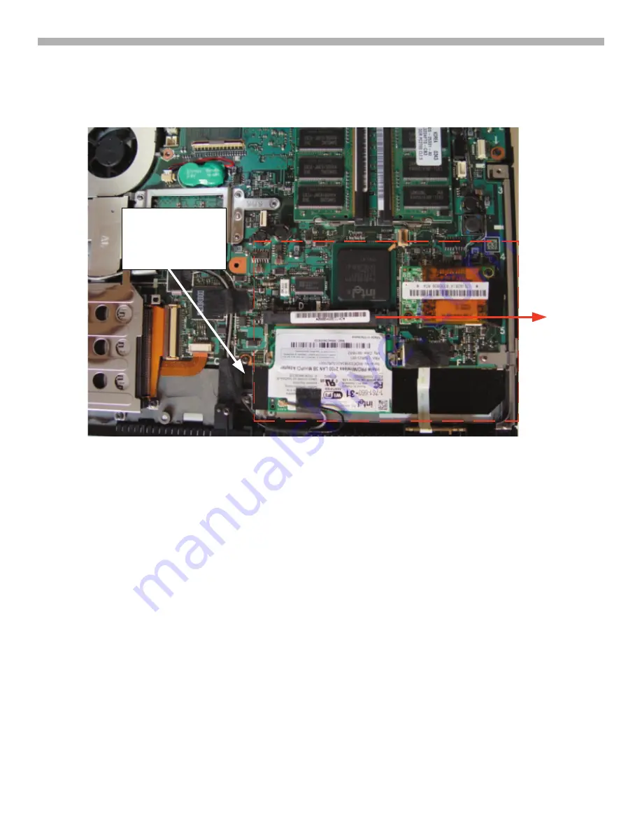
Wireless LAN
Step 1
: Lift one side of each of the 5 pieces of cloth tape securing the two wireless LAN antenna cables as shown
in Figure 2-9. Lift one side of the copper tape securing the cables to the cooling fan assembly. NOTE: If you are
going to replace the motherboard, remove the tape pieces completely as they will have to be transferred to the
replacement board. Some models may only have 4 pieces of cloth tape. It depends on what type of wireless LAN
assembly is used.
Step 2
: Spread the locking tabs as shown in Figure 2-10. It is the same procedure as removing memory modules.
Unplug the two antenna cables noting the location of the gray and black cables.
Step 3
: Undress the cables from the motherboard and fan. Note the slots in the lower cabinet and markings
on the motherboard indicating the proper routing of the cable when it is re-installed later. This is important to
minimize interference. Also note the positioning of the cables inside the hinge assembly of the LCD panel as
illustrated in Figure 2-11. This is important to prevent pinching the cables when re-assembling the unit.


