


1-12
UP-960(UC)
UP-960CE(CE)
50
Specifications
Thermal head
Thin-film thermal head (with built-in drive
IC ) 1280 dots
Gradation
256
Picture elements
EIA: 1280
×
507 dots
CCIR: 1280
×
607 dots
Print size (at factory setting)
STANDARD mode and WIDE 1 mode
EIA: 190
×
144 mm
CCIR: 190
×
142 mm
SIDE mode
EIA: 243
×
184 mm
CCIR: 243
×
181 mm
Printing speed
EIA: About 10 seconds/screen (aspect
ratio 4:3)
CCIR: About 12 seconds/screen (aspect
ratio 4:3)
Picture memory
2048
×
1024
×
8 bits
Input/output connectors
VIDEO IN (BNC)
EIA or CCIR Composite video signals
1.0 Vp-p, 75 ohms/high-impedance (EIA/
CCIR automatically discriminated)
VIDEO OUT (BNC)
EIA or CCIR Composite video signals
1.0 Vp-p, 75 ohms, loop-through
REMOTE (stereo minijack)
Power requirements and consumption
120 V AC, 50/60 Hz, 2.4 A
220 to 240 V AC, 50/60 Hz, 1.3 A
Operating temperature
5
°
C to 35
°
C (41
°
F to 95
°
F)
Operating humidity
20 % to 80 % (no condensation allowed)
Storage and transport temperature
-20
°
C to 60
°
C (-4
°
F to 140
°
F)
Storage and transport humidity
20 % to 90 % (no condensation allowed)
Dimensions
Approx. 316
×
132
×
305 mm (w/h/d) (12
1
⁄
2
×
5
1
⁄
4
×
12
1
⁄
8
inches)
Mass
Approx. 8 kg (17 lb 10 oz), Main unit only
Supplied accessories
Paper roll (UPP-210HD) (1)
BNC – BNC connecting cable (1)
AC power cord (1)
Head cleaning sheet (1)
Instructions for Use (1)
Design and specifications are subject to change
without notice.
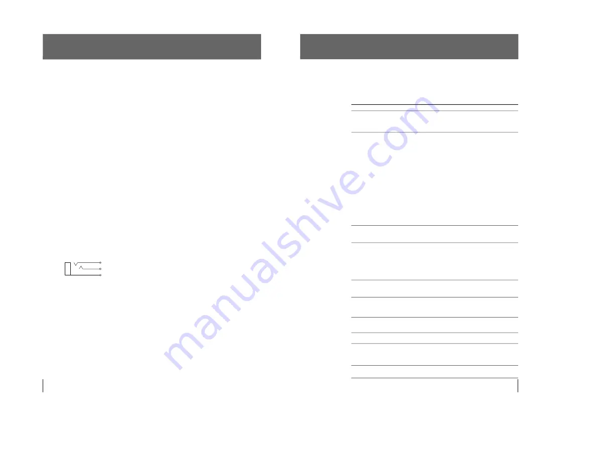
Others
3
2
1
1 GND
2 PRINT SIGNAL (TTL)
When the LOW pulse over 100 msec is
input, printing starts.
3 PRINT BUSY (TTL)
Goes HIGH during printing.
51
Troubleshooting
The following troubleshooting checks will help you correct the most common
problems you may encounter with your printer. Before proceeding with these
trouble check, first check that the power cord is firmly connected. should the
problem persist, unplug the printer and contact your Sony dealer or local
authorized Sony service facility.
Symptom
White specks on first few
printouts.
Printing does not start
when you press the PRINT
or COPY button.
Black borders or missing
portions around
the printout.
Paper jam
Printout is dirty.
The printer stops printing
when it prints continuously
dark images.
(The alarm buzzer sounds.)
White lines or small letters
on the screen are not
printed clearly.
Small squares appear over
the whole screen.
The printout is too dark
or too light.
The printout seems
stretched.
Cause/remedy
When printing with a newly inserted roll of paper, dust on the
surface of the paper may cause white specks on the printouts.
n
Feed the paper by pressing the FEED button until clean
paper appears, then tear off the paper by your hand.
• Paper does not feed.
n
Is the paper slack? (page 40)
n
Is the power turned on?
n
Are all connections correct? (page 33)
n
Did you press the PRINT button twice in SMALL mode?
(page 42)
• When the alarm buzzer sounds:
n
Has the thermal head overheated? The thermal head
may overheat when the printer prints dark image
continuously. In such a case, the PAPER/EMPTY
indicator blinks. Wait until the head cools down.
n
Is the video signal of the picture input?
n
Is the paper loaded correctly?
• Paper feeds, but printing does not start.
n
Is the paper loaded with the thermo-sensitive side up?
(page 40)
This may result according to the video signal input to the
printer.
n
Change the setting of SCAN switches. (page 37)
• Open the door panel by pressing the OPEN/CLOSE button,
then slowly pull out the jammed paper slowly and remove it.
• There is condensation within the unit.
n
Moving the unit suddenly from a cold place to a warm
place often results in condensation forming. In the event
of condensation forming, remove the paper, turn off the
power and leave the unit for about one to two hours.
The thermal head is dirty.
n
Clean the thermal head with the supplied head cleaning
sheet. (page 47)
This is likely to occur when the printer continuously prints 15
or more dark pictures. In such a case, the buzzer sounds. This
is because there is the protective circuit that guards against
heat buildup of the thermal head. Stop printing for a while.
Is the INPUT switch of the DIP switches to B & W (ON) when
the input signal is a black and white signal? (page 36)
Is the INPUT switch of the DIP switches to COLOR (OFF)
when the input signal is a color signal? (page 36)
• Is the 75 ohm switch of the DIP switches set correctly?
(page 36)
• Is the GAMMA switches of the DIP switches set correctly?
(page 35)
Is the ASPECT switch of the DIP switches set to 1:1?
n
Set to 4:3. (page 38)
Others
Содержание UP-960
Страница 1: ...VIDEO GRAPHIC PRINTER UP 960 UP 960CE 1st Edition SERVICE MANUAL ...
Страница 6: ......
Страница 20: ......
Страница 26: ......
Страница 46: ......
Страница 74: ......
Страница 75: ...8 1 8 1 UP 960 UC UP 960CE CE SECTION 8 BLOCK DIAGRAMS ...
Страница 92: ......


