— 22 —
KV-21ME43
KV-21ME43
KV-21ME43
KV-21ME43
KV-21ME43
5-4.
5-4.
5-4.
5-4.
5-4. A
A
A
A
A BOARD
BOARD
BOARD
BOARD
BOARD ADJUSTMENTS
ADJUSTMENTS
ADJUSTMENTS
ADJUSTMENTS
ADJUSTMENTS
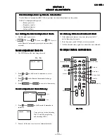
H. Frequency Adjustment
H. Frequency Adjustment
H. Frequency Adjustment
H. Frequency Adjustment
H. Frequency Adjustment
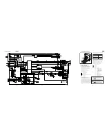
1. Input a monoscope signal.
2. Set to Service Adjustment Mode.
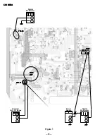
3. Connect a frequency counter to base of Q501
(TP-500 H. DRIVE).
4. Select the item of AFC, set to 3 level (free run).
5. Check H. Frequency for the 15735 ± 200 Hz.
6. Select the AFC item again and adjust level to 0.
7. Press
then
to save into the memory.
V
V
V
V
V. Frequency
. Frequency
. Frequency
. Frequency
. Frequency Adustment
Adustment
Adustment
Adustment
Adustment
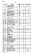
1. Select video 1 with no signal input.
2. Set the conditions for a standard setting.
3. Connect the frequency counter across TP-508 or CN501
VDY (+) pin
connector and ground.
4. Check that V. Frequency shows 60 ± 2 Hz.
Sub Contrast
Sub Contrast
Sub Contrast
Sub Contrast
Sub Contrast Adjustment (RDR
Adjustment (RDR
Adjustment (RDR
Adjustment (RDR
Adjustment (RDRV)
V)
V)
V)
V)
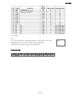
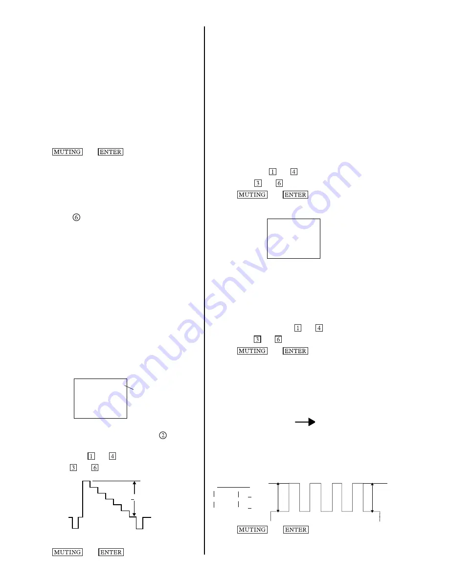
1. Input a color-bar signal.
2. Set the red color.
3. Set to Service Adjustment Mode.
4. Select the item DCOL level to 0.
5. Set the conditions as follows:
PICTURE:
MAX
COLOR:
MIN
BRIGHT:
CENTER
R ON:
ON (1)
G ON:
OFF (0)
B ON:
OFF (0)
SERVICE RON 1
1: ON
0: OFF
6. Connect an oscilloscope probe to CN301 pin
(R OUT) and ground.
7. Select RDRV with
and
.
8. Adjust with
and
for 1.50 ± 0.1 Vp-p
Black
White
1.70 ± 0.05 Vp-p
9. Reset the item DCOL to 1.
10. Press
then
to save into the memory.
11. Return the following back to normal after adjustment.
PICTURE:
MAX
COLOR:
CENTER
BRIGHT:
CENTER
R ON:
ON (1)
G ON:
OFF (0)
B ON:
OFF (0)
Display Position
Display Position
Display Position
Display Position
Display Position Adjustment (DISP)
Adjustment (DISP)
Adjustment (DISP)
Adjustment (DISP)
Adjustment (DISP)
1. Input a color-bar signal.
2. Set to Service Adjustment Mode.
3. Select DISP with
and
.
4. Adjust with
and
to adjust characters to the center.
5. Press
then
to save into the memory.
6. Check to see if the text is displayed on the screen.
SERVICE DISP 15
Sub Bright
Sub Bright
Sub Bright
Sub Bright
Sub Bright Adjustment (SBRT)
Adjustment (SBRT)
Adjustment (SBRT)
Adjustment (SBRT)
Adjustment (SBRT)
1. Input a crosshatch signal.
2. Set to Service Adjustment Mode.
3. Set the PICTURE and BRIGHTNESS to minimum.
4. Select the SBRT item with
and
.
5. Adjust with
and
to obtain a faintly visible crosshatch.
6. Press
then
to save into the memory.
Sub Hue, Sub Color
Sub Hue, Sub Color
Sub Hue, Sub Color
Sub Hue, Sub Color
Sub Hue, Sub Color Adjustment (SHUE, SCOL)
Adjustment (SHUE, SCOL)
Adjustment (SHUE, SCOL)
Adjustment (SHUE, SCOL)
Adjustment (SHUE, SCOL)
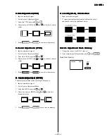
1. Input a color-bar signal.
2. Set to Service Adjustment Mode.
3. Select the DCOL item and set the value to 0.
4. Connect a probe to TP47B
B-OUT (C Board).
4.1)
Decrease SCOL Register -1 step (only for Q, R, S).
5. Measure white V1 & blue V4.
5.1)
Increase SCOL Re 1 step (only for Q, R, S).
6. Reset the DCOL level to 1.
7. Press
then
to save into the memory.
1.50 + 0.1 Vpp
V1
V2
V3
V4
STANDARD
V4 - V1 = + 0.20
V3 - V2 = + 0.20
Содержание TRINITRON RM-Y156
Страница 24: ... 24 KV 21ME43 KV 21ME43 KV 21ME43 KV 21ME43 KV 21ME43 NOTES ...
Страница 25: ... 25 KV 21ME43 KV 21ME43 KV 21ME43 KV 21ME43 KV 21ME43 NOTES ...
Страница 26: ... 26 KV 21ME43 KV 21ME43 KV 21ME43 KV 21ME43 KV 21ME43 NOTES ...
Страница 38: ... 86 NOTES NOTES 50 KV 21ME43 KV 21ME43 KV 21ME43 KV 21ME43 KV 21ME43 ...


