background image

– 38 –

10

Getting Started

Step 5:  Setting the clock (continued)

6

Press 

M

m

 or 

,

 to set the month, year, hour and minutes in

the same way as in step 

5

, then press ENTER.

The clock starts working.

To return to the normal screen

Press MENU.

If you have made a mistake while setting the clock

Press 

<

 to go back to the item to be changed and set the correct

digits using 

M

 or 

m

, then press 

,

.

Note

• If power is interrupted or you disconnect the AC power cord, you have to

re-set the clock.

11

Getting Started

Getting Started

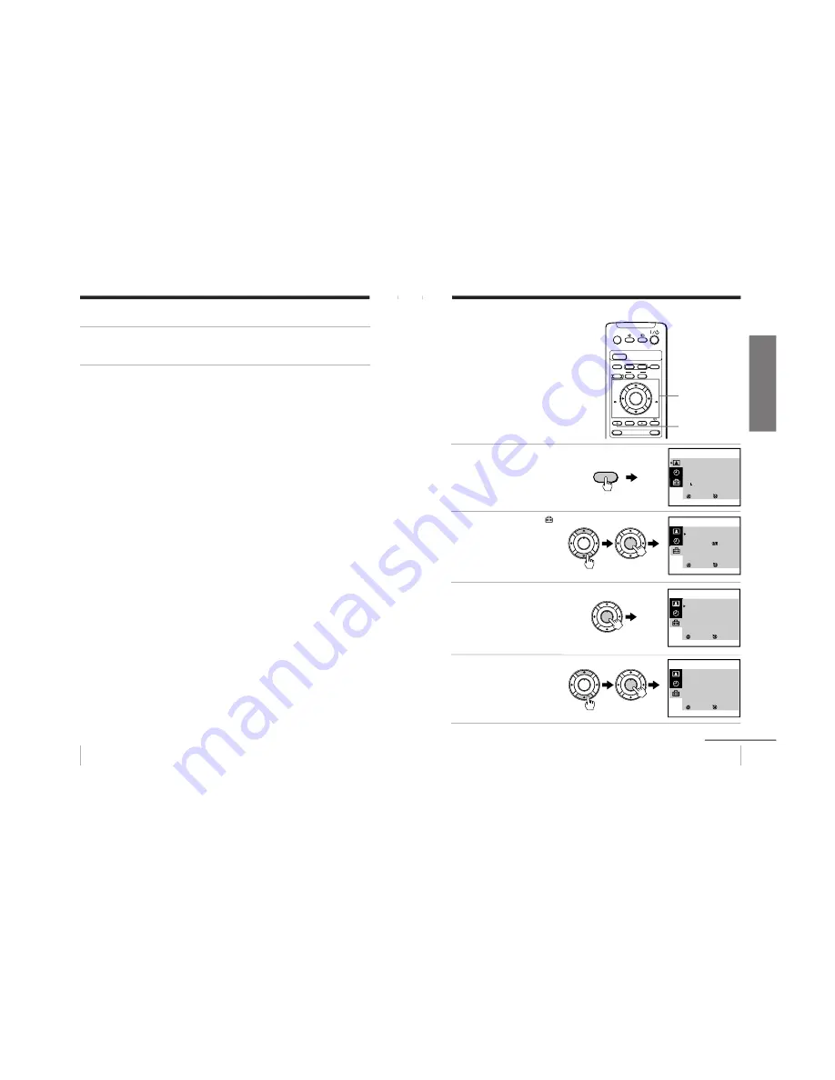
Step 6:  Setting the channels

Presetting channels
automatically

You can preset up to 100 channels.

Automatic presetting is the easiest way
to setup your video TV if you want to
preset all receivable channels at once.

To preset the channels manually, see
page 34.

1

Press MENU.

2

Press 

M

 or 

m

 to select 

 ,

then press ENTER.

3

Make sure TV SET UP is
selected, then press
ENTER.

4

Press 

M

 or 

m

 to select TV

SYS, then press ENTER.

The selected item turns red.

Press 

M

 or 

m

 to select the

TV system (B/G, I, D/K or
M) and press ENTER.

continued

COUNTER RESET

t

MENU

REW

A/B

EJECT

TIMER REC

G-CODE

ON/OFF

TAPE SPEED

INDEX

z

REC

GAME

PAUSE

STOP

m

FF

M

Z

.

>

PLAY

ENTER

PIC MODE

H

M

/

,

/

m

/

<

/

ENTER

MENU

SELECT

PICTURE MODE
 

·

DYNAMIC


·

STANDARD


·

SOFT


·

PERSONAL

     ADJUST

3

ENTER

SELECT

SET UP
TV SET UP
VIDEO SET UP
LANGUAGE/      :ENGLISH
PIC ROTATION

3

ENTER

SELECT

TV SET UP
AUTO PROGRAM
MANUAL PROGRAM
SKIP :  PR  01  OFF
TV SYS :  B/G
COL SYS :  AUTO
INTELLIGENT VOL : OFF

3

ENTER

MENU

PLAY

ENTER

H

PLAY

ENTER

H

PLAY

ENTER

H

PLAY

ENTER

H

PLAY

ENTER

H

SELECT

TV SET UP
AUTO PROGRAM
MANUAL PROGRAM
SKIP :  PR  01  OFF
TV SYS :  B/G
COL SYS :  AUTO
INTELLIGENT VOL : OFF

3

ENTER

Содержание TRINITRON KV-VF21M70

Страница 1: ...RM 955 HK SCC P09A A 21 Please file according to model size TRINITRON COLORVIDEOTV COUNTERRESET t MENU REW A B EJECT TIMERREC G CODE ON OFF TAPESPEED INDEX zREC GAME 2 PROGR 1 6 7 0 C 9 4 3 2 5 8 X PAUSE x STOP m FF M Z PLAY ENTER PIC MODE H COUNTERRESET t MENU REW EJECT TIMERREC G CODE ON OFF TAPESPEED INDEX zREC GAME 2 PROGR 1 6 7 0 C 9 4 3 2 5 8 X PAUSE x STOP m FF M Z PLAY ENTER PIC MODE H RM ...

Страница 2: ...ing time PAL MESECAM SP 240 minutes with E 240 LP 480 minutes with E 240 NTSC SP 180 minutes with T 180 EP 540 minutes with T 180 Inputs and Outputs Inputs t1 t2 GAME IN video phono jack 1 Vp p 75 ohms unbalanced sync negative 9 audio phono jack Input level 500 mVrms Headphones jack Minijack General Clock Quartz locked Power requirements 110 240 V AC 50 60Hz Power consumption 123 W Operating tempe...

Страница 3: ... Africa 4 to 13 C04 to C13 21 to 68 C21 to C68 Angola 1 C00 2 to 3 C02 to C03 CATV S 01 to S 05 S42 to S46 S 1 to S41 S01 to S41 D K K1 East European R 1 to R 12 C01 to C12 coutries R 21 to R 60 C21 to C60 China C 1 C01 C 2 C02 C 3 C13 C 4 C03 C 5 C04 C 6 C14 C 7 to C 12 C06 to C11 C 13 to C 24 C21 to C32 C 25 to C 47 C38 to C60 C 48 to C 57 C61 to C70 Ivory Coast 1 to 3 C71 to C73 CATV S 1 to S 3...

Страница 4: ...DING AND MARK ON THE SCHEMATIC DIAGRAMS EXPLODED VIEWS AND IN THE PARTS LIST ARE CRITICAL FOR SAFE OPERATION REPLACE THESE COMPONENTS WITH SONY PARTS WHOSE PART NUMBERS APPEAR AS SHOWN IN THIS MANUAL OR IN SUP PLEMENTS PUBLISHED BY SONY CIRCUIT ADJUSTMENTS THAT ARE CRITICAL FOR SAFE OPERATION ARE IDENTIFIED IN THIS MANUAL FOLLOW THESE PROCEDURES WHEN EVER CRITICAL COMPONENTS ARE REPLACED OR IM PRO...

Страница 5: ...ty Note 1 If a B overcurrent is detected stoppage of the vertical deflection is detected simultaneously The symptom that is diagnosed first by the microcontroller is displayed on the screen Note 2 Refer to screen G2 Adjustment in section 3 4 of this manual SELF DIAGNOSTIC FUNCTION FBT Q802 H OUT shorted 2 0 or 2 1 4 1 2 times 4 times 5 times Vertical deflection stopped White balance failure no PIC...

Страница 6: ...lts after completion of the repairs Clearing the result display To clear the result display to 0 press buttons on the remote commander sequentially as shown below when the diagnos tic screen is being displayed Pay attention when perform by the service mode other all electric adjustment data will be rewrite Channel 8 0 Quitting Self diagnostic screen To quit the entire self diagnostic screen turn o...

Страница 7: ...utomatic white balance detecting standard pulse which detect cathode current or which become low almost CRT 7 3 62 52 60 49 47 41 A 42 43 A 37 21 34 35 15 SCL1 SDA1 V PULSE LED1 OVP VCR RY601 RELAY Q601 ITEM 2 Over voltage Detection OCP BOOST VCC IC501 IC301 Y C J HP PROTECT SDA SCL IK IN VM OUT R G B STOP To item 2 and 5 via bus line MEMORY V STOP IC004 R G B ITEM 5 Auto cut off white balance det...

Страница 8: ...ies Stabilizer band Two clamps Two wood screws AC plug adaptor These operating instructions Insert the batteries into the remote control Note Do not use old batteries or different types of batteries together 5 Getting Started Getting Started Step 2 Installing the video TV Secure the video TV To prevent the video TV from falling secure it using one of the following methods A With the supplied screw...

Страница 9: ...ntenna or Rear 300 ohm twin lead cable VHF UHF mixer not supplied UHF antenna VHF antenna 7 Getting Started Getting Started Step 4 Selecting the language You can change the menu and on screen information language to Chinese 1 Press 1 to turn on the video TV When the TV is in standby mode the 1 indicator on the video TV is lit in red press 1 PROGR or a number button on the remote control 2 Press ME...

Страница 10: ...ecording and on timer functions 1 Press MENU 2 Press M or m to select then press ENTER 3 Press M or m to select CLOCK SET then press ENTER 4 Press ENTER The day section turns red 5 Press M or m to set the day then press The month section turns red continued A B G CODE COUNTERRESET t MENU REW EJECT TIMERREC ON OFF TAPESPEED INDEX zREC GAME 1 3 2 X PAUSE x STOP m FF M Z PLAY ENTER PIC MODE H M m ENT...

Страница 11: ...annels at once To preset the channels manually see page 30 1 Press MENU 2 Press M or m to select then press ENTER 3 Make sure TV SET UP is selected then press ENTER 4 Press M or m to select TV SYS then press ENTER The selected item turns red Press M or m to select the TV system B G I D K or M and press ENTER continued A B G CODE COUNTERRESET t MENU REW EJECT TIMERREC ON OFF TAPESPEED INDEX zREC GA...

Страница 12: ... 1 AUTO PROGRAM PR 01 TV SYS B G CH 01 3 ENTER PLAY ENTER H PLAY ENTER H 13 Getting Started Getting Started 1 Press 1 to turn on the video TV When the TV is in standby mode the 1 indicator on the video TV is lit in red press 1 PROGR or a number button on the remote control 2 Press TUNER PRESET ON OFF with a pointed object Do not use an item such as a pencil that might break off when inserted 3 Pre...

Страница 13: ...sic Operations Additional tasks To Press Turn off temporarily 1 on the remote control The 1 indicator on the video TV lights up in red Turn off the main power 1 on the video TV The w indicator on the video TV lights up in orange Adjust the volume 2 Mute the sound Watch the video input t to select t1 or t2 see page 48 from a connected VCR To return to the TV screen press t again camcorder etc Selec...

Страница 14: ...Wm STOPx PLAY ENTER H 17 Basic Operations Additional tasks To Press stop playback STOP x The video TV goes back to the normal TV picture stop playback for a moment PAUSE X Press PAUSE X again or press PLAY N to resume playback If you leave your video TV in pause mode normal playback resumes after about 5 minutes to prevent tape damage search a tape at high speed REW m rewind or FF M fast forward d...

Страница 15: ...f remaining tape Beginning of the tape End of the tape Tape operation mode Linear tape counter Tape speed Current date and time 19 Basic Operations Recording TV programs Recording TV programs 1 Press 1 to turn on the video TV If the TV is in standby mode the 1 indicator on the video TV is lit in red the video TV will turn on automatically when a cassette is inserted 2 Insert a cassette with a safe...

Страница 16: ...for about 5 minutes the video TV stops recording to prevent tape damage Recording with the TV off Press 1 on the video TV The video TV is turned off and the w indicator lights up The video TV continues recording zREC 21 Basic Operations Selecting the tape speed The chart below shows the recording playback time available in each mode PAL MESECAM Cassette tape Tape speed setting SP mode LP mode E 30...

Страница 17: ...g timer recordings A B G CODE COUNTERRESET t MENU REW EJECT TIMERREC ON OFF TAPESPEED INDEX zREC GAME X PAUSE x STOP m FF M Z PLAY ENTER PIC MODE H QUICK TIMER TAPE SPEED QUICK TIMER PUSH SELECT START OK CHANGE CLEAR TAPE SPEED SP 27SAT 20 00 0H 15M 12 PROG QUICK TIMER 27 SAT 20 00 ENTER TAPESPEED 23 Basic Operations 3 Turn QUICK TIMER to set the hour of the start time then press QUICK TIMER The h...

Страница 18: ...pear depending on the cassette used If a message appears the recording is canceled Put in a tape The program recording is canceled Put in a tape with safety tab The program recording is canceled Tape ran out The program recording is canceled Insert a cassette for recording rewind the tape and press QUICK TIMER again 25 Basic Operations Changing or canceling the Quick Timer settings 1 Press QUICK T...

Страница 19: ... start time recording stop time program position input 1 or 2 and tape speed in the same way as in step 2 4 Press ENTER The cursor appears at OK For daily and weekly recording see Daily weekly recording below 5 Press or to move the cursor to NEXT for other programs then press ENTER Repeat steps 2 through 4 6 Press or to move the cursor to OK after setting your desired programs then press ENTER The...

Страница 20: ...F TAPESPEED INDEX zREC X PAUSE x STOP m FF M PLAY ENTER PIC MODE H TIMER REC M m ENTER PROGRAM LIST 27 SAT 20 00 DATE START STOP PRG 28 SUN 21 00 22 00 6 SP 29 MON 1 30 3 00 79 LP MON SAT 18 50 19 00 2 SP EVERYTUE21 00 23 30 1 LP OK SET ENTER SELECT ADD CHANGE CLEAR Programmed as below TIMERREC 29 Additional Operations Additional Operations Adjusting the TV Adjusting the volume INTELLIGENT VOL Som...

Страница 21: ...then press ENTER You can also select the channel number directly with the number buttons Press C once for regular channels twice for cable channels the desired number buttons then ENTER PLAY ENTER H PLAY ENTER H SELECT MANUAL PROGRAM PR 01 TV SYS B G CH 01 FINE AUTO 3 ENTER 31 Additional Operations 7 If the sound of the desired channel is abnormal select the appropriate TV system 1 Press M or m to...

Страница 22: ... steps 5 and 6 to skip other program positions To return to the normal screen Press MENU PLAY ENTER H PLAY ENTER H SELECT TV SET UP AUTO PROGRAM MANUAL PROGRAM SKIP PR 07 ON TV SYS B G COL SYS AUTO INTELLIGENT VOL OFF 3 ENTER 33 Additional Operations Adjusting the TV system If the sound of some channels is abnormal select the appropriate TV system for your area 1 Press MENU 2 Press M or m to selec...

Страница 23: ...djust the picture quality 1 Press MENU 2 Press M or m to select then press ENTER 3 Press M or m to select ADJUST then press ENTER 4 Press M or m to select the desired item then press ENTER The adjustment bar for the selected item appears at the bottom of the screen 5 Adjust the value according to the following table then press ENTER For Press m to Press M to PICTURE decrease picture contrast incre...

Страница 24: ...OTATION 37 Additional Operations Tape options Adjusting the tracking Adjusting the tracking automatically The tracking condition is automatically adjusted when this function is set to AUTO Adjusting the tracking manually If streaks or snow noise appear during normal playback adjust the tracking 1 Press MENU in playback mode 2 Press M or m to select then press ENTER 3 Press M or m to select VIDEO S...

Страница 25: ...S OTHERS COL SYS AUTO 3 ENTER SELECT VIDEO SET UP TRACKING AUTO APC OFF AUTO REPEAT OFF RENTAL OFF VHS OTHERS COL SYS AUTO 3 ENTER PLAY ENTER H PLAY ENTER H PLAY ENTER H PLAY ENTER H 39 Additional Operations Playing a tape repeatedly You can play the recorded portion of a tape repeatedly 1 Press MENU 2 Press M or m to select then press ENTER 3 Press M or m to select VIDEO SET UP then press ENTER 4...

Страница 26: ...VHS OTHERS COL SYS AUTO 3 ENTER PLAY ENTER H PLAY ENTER H PLAY ENTER H PLAY ENTER H 41 Additional Operations When connecting to a Sony VCR If you use this video TV with another Sony VCR the remote control may accidentally operate both the video TV and VCR at the same time To prevent this from happening set VHS to SONY so that the remote control operates only this video TV 1 Press MENU 2 Press M or...

Страница 27: ... in To return to the normal screen Press MENU SELECT VIDEO SET UP TRACKING AUTO APC ON AUTO REPEAT OFF RENTAL OFF VHS OTHERS COL SYS PAL 3 ENTER PLAY ENTER H PLAY ENTER H 43 Additional Operations Switching off automatically SLEEP You can automatically switch the video TV into standby mode after a selected time period Press With each press the time period in minutes changes as illustrated One minut...

Страница 28: ...press ENTER A B G CODE COUNTERRESET t MENU REW EJECT TIMERREC ON OFF TAPESPEED INDEX zREC GAME X PAUSE x STOP m FF M Z PLAY ENTER PIC MODE H M m ENTER MENU ON TIMER SET DAY S M T W T F S TIME 10 00 SOURCE TV PROG 12 ON TIMER ON 3 SELECT ENTER _ _ _ _ _ PLAY ENTER H 45 Additional Operations 9 Press M or m to set the source to be switched on then press ENTER The SOURCE changes as follows TV PROG t V...

Страница 29: ...earch backwards press INDEX The video TV starts searching and the index number on the TV screen counts down to zero Playback starts automatically from that point To stop searching Press STOP x A B G CODE COUNTERRESET t MENU REW EJECT TIMERREC ON OFF TAPESPEED INDEX zREC GAME X PAUSE x STOP m FF M Z PLAY ENTER PIC MODE H STOP x INDEX INDEX 5 SEARCH INDEX 47 Additional Operations Connecting optional...

Страница 30: ...ons To connect a video game To display the video game screen Press GAME when the video TV is in standby mode To switch to a TV program Press the number button on the remote control PROGR or t on the video TV or remote control To switch to the VCR Press the PLAY N button on the video TV or remote control when a cassette is in the video TV A B G CODE COUNTERRESET t MENU REW EJECT TIMERREC ON OFF TAP...

Страница 31: ...ss 1 or a program number button on the remote control Good picture No sound The volume level is too low The sound is muted Headphones are connected to i headphones jack Press 2 to increase the volume level Press to cancel the muting Disconnect the headphones No color or poor color The color level setting is too low The picture setting is inappropriate The color system setting is inappropriate The ...

Страница 32: ...her equipment away from the video TV Press 1 on the video TV to turn off the video TV for about five minutes then turn on again Clock and timer section The clock has stopped and is displayed The power has been interrupted or the AC power cord is disconnected Re set the clock and timer settings page 9 53 Additional Information Symptom Possible cause Solutions Playback section Power is on but the ta...

Страница 33: ...cassette is ejected when you press REC z The safety tab of the cassette has been removed Cover the safety tab hole with adhesive tape or use another cassette with its safety tab intact Cannot record No cassette has been inserted The tape is at its end Insert a cassette with its safety tab intact Rewind the tape Timer recording section Cannot program a recording using the timer The clock has not be...

Страница 34: ...standby button 14 7 PIC MODE picture mode button 15 8 Menu operation buttons 26 MENU button V B v b buttons ENTER button 9 GAME button 49 q Number buttons 19 qa PROGR buttons 19 A B G CODE COUNTERRESET t MENU REW EJECT TIMERREC ON OFF TAPESPEED INDEX zREC GAME 2 PROGR 1 6 7 0 C 9 4 3 2 5 8 X PAUSE x STOP m FF M Z PLAY ENTER PIC MODE H 1 5 7 6 9 8 q qa 2 3 4 A B G CODE COUNTERRESET t MENU REW EJECT...

Страница 35: ...s into the remote control Note Do not use old batteries or different types of batteries together 5 Getting Started Getting Started Step 2 Installing the video TV Secure the video TV To prevent the video TV from falling secure it using one of the following methods A With the supplied screws attach the stabilizer band to the TV stand and to the rear of the video TV using the existing hole OR B Pass ...

Страница 36: ...antenna or Rear 300 ohm twin lead cable VHF UHF mixer not supplied UHF antenna VHF antenna 7 Getting Started Getting Started Step 4 Selecting the language You can change the menu and on screen information language to Chinese 1 Press 1 to turn on the video TV When the TV is in standby mode the 1 indicator on the video TV is lit in red press 1 PROGR or a number button on the remote control 2 Press M...

Страница 37: ...ecording and on timer functions 1 Press MENU 2 Press M or m to select then press ENTER 3 Press M or m to select CLOCK SET then press ENTER 4 Press ENTER The day section turns red 5 Press M or m to set the day then press The month section turns red continued COUNTERRESET t MENU REW A B EJECT TIMERREC G CODE ON OFF TAPESPEED INDEX zREC GAME 1 3 2 X PAUSE x STOP m FF M Z PLAY ENTER PIC MODE H M m ENT...

Страница 38: ...annels at once To preset the channels manually see page 34 1 Press MENU 2 Press M or m to select then press ENTER 3 Make sure TV SET UP is selected then press ENTER 4 Press M or m to select TV SYS then press ENTER The selected item turns red Press M or m to select the TV system B G I D K or M and press ENTER continued COUNTERRESET t MENU REW A B EJECT TIMERREC G CODE ON OFF TAPESPEED INDEX zREC GA...

Страница 39: ... 1 AUTO PROGRAM PR 01 TV SYS B G CH 01 3 ENTER PLAY ENTER H PLAY ENTER H 13 Getting Started Getting Started 1 Press 1 to turn on the video TV When the TV is in standby mode the 1 indicator on the video TV is lit in red press 1 PROGR or a number button on the remote control 2 Press TUNER PRESET ON OFF with a pointed object Do not use an item such as a pencil that might break off when inserted 3 Pre...

Страница 40: ...ations Additional tasks To Press Turn off temporarily 1 on the remote control The 1 indicator on the video TV lights up in red Turn off the main power 1 on the video TV The w indicator on the video TV lights up in orange Adjust the volume 2 Mute the sound Watch the video input t to select t1 or t2 see page 53 from a connected VCR To return to the TV screen press t again camcorder etc Selecting the...

Страница 41: ...Wm STOPx PLAY ENTER H 17 Basic Operations Additional tasks To Press stop playback STOP x The video TV goes back to the normal TV picture stop playback for a moment PAUSE X Press PAUSE X again or press PLAY N to resume playback If you leave your video TV in pause mode normal playback resumes after about 5 minutes to prevent tape damage search a tape at high speed REW m rewind or FF M fast forward d...

Страница 42: ...f remaining tape Beginning of the tape End of the tape Tape operation mode Linear tape counter Tape speed Current date and time 19 Basic Operations Recording TV programs Recording TV programs 1 Press 1 to turn on the video TV If the TV is in standby mode the 1 indicator on the video TV is lit in red the video TV will turn on automatically when a cassette is inserted 2 Insert a cassette with a safe...

Страница 43: ...for about 5 minutes the video TV stops recording to prevent tape damage Recording with the TV off Press 1 on the video TV The video TV is turned off and the w indicator lights up The video TV continues recording zREC 21 Basic Operations Selecting the tape speed The chart below shows the recording playback time available in each mode PAL MESECAM Cassette tape Tape speed setting SP mode LP mode E 30...

Страница 44: ... TAPESPEED INDEX zREC GAME X PAUSE x STOP m FF M Z PLAY ENTER PIC MODE H QUICK TIMER TAPE SPEED A B QUICK TIMER PUSH SELECT START OK CHANGE CLEAR TAPE SPEED SP A B MAIN 27SAT 20 00 0H 15M 12 PROG QUICK TIMER 27 SAT 20 00 ENTER TAPESPEED 23 Basic Operations 3 Turn QUICK TIMER to set the hour of the start time then press QUICK TIMER The hour is set and the minute of the start time turns red 4 Turn Q...

Страница 45: ...depending on the cassette used If a message appears the recording is canceled Put in a tape The program recording is canceled Put in a tape with safety tab The program recording is canceled Tape ran out The program recording is canceled Insert a cassette for recording rewind the tape and press QUICK TIMER again 25 Basic Operations Changing or canceling the Quick Timer settings 1 Press QUICK TIMER ...

Страница 46: ... PROGR or a number button on the remote control COUNTERRESET t MENU REW A B EJECT TIMERREC G CODE ON OFF TAPESPEED INDEX zREC GAME 1 3 2 X PAUSE x STOP m FF M Z PLAY ENTER PIC MODE H 1 MENU M m ENTER 27 Basic Operations 1 Press MENU 2 Press M or m to select then press ENTER 3 Make sure TV SET UP is selected then press ENTER 4 Press M or m to select MANUAL PROGRAM then press ENTER 5 Make sure PR is...

Страница 47: ...P or LP EP cannot be selected when making timer recordings 3 Press the number buttons to enter the program s G CODE number 4 Press ENTER The date start and stop times program position tape speed and sound mode appears on the TV screen If you want to change the sound mode press A B to select MAIN or SUB 5 Repeat steps 2 through 4 to enter other settings You can set up to five programs in a one mont...

Страница 48: ...ations 3 Set the recording start time recording stop time program position input 1 or 2 tape speed and sound mode in the same way as in step 2 4 Press ENTER The cursor appears at OK For daily and weekly recording see Daily weekly recording below 5 Press or to move the cursor to NEXT for other programs then press ENTER Repeat steps 2 through 4 6 Press or to move the cursor to OK after setting your ...

Страница 49: ...APESPEED INDEX zREC X PAUSE x STOP m FF M PLAY ENTER PIC MODE H TIMER REC M m ENTER PROGRAM LIST 27 SAT 20 00 DATE START STOP PRG A B 28 SUN 21 00 22 00 6SPMAIN 29 MON 1 30 3 00 79LP SUB MON SAT 18 50 19 00 2SPMAIN EVERYTUE21 00 23 30 1LP SUB OK SET ENTER SELECT ADD CHANGE CLEAR Programmed as below TIMERREC 33 Additional Operations Additional Operations Adjusting the TV Adjusting the volume INTELL...

Страница 50: ...NTER PLAY ENTER H PLAY ENTER H SELECT MANUAL PROGRAM PR 01 TV SYS B G CH 01 FINE AUTO GUIDE CH 01 3 ENTER 35 Additional Operations 7 If the sound of the desired channel is abnormal select the appropriate TV system 1 Press M or m to select TV SYS then press ENTER 2 Press M or m until the sound becomes normal then press ENTER 8 If you are not satisfied with the picture and sound quality you may be a...

Страница 51: ... steps 5 and 6 to skip other program positions To return to the normal screen Press MENU PLAY ENTER H PLAY ENTER H SELECT TV SET UP AUTO PROGRAM MANUAL PROGRAM SKIP PR 07 ON TV SYS B G COL SYS AUTO INTELLIGENT VOL OFF 3 ENTER 37 Additional Operations Adjusting the TV system If the sound of some channels is abnormal select the appropriate TV system for your area 1 Press MENU 2 Press M or m to selec...

Страница 52: ...djust the picture quality 1 Press MENU 2 Press M or m to select then press ENTER 3 Press M or m to select ADJUST then press ENTER 4 Press M or m to select the desired item then press ENTER The adjustment bar for the selected item appears at the bottom of the screen 5 Adjust the value according to the following table then press ENTER For Press m to Press M to PICTURE decrease picture contrast incre...

Страница 53: ...OTATION 41 Additional Operations Tape options Adjusting the tracking Adjusting the tracking automatically The tracking condition is automatically adjusted when this function is set to AUTO Adjusting the tracking manually If streaks or snow noise appear during normal playback adjust the tracking 1 Press MENU in playback mode 2 Press M or m to select then press ENTER 3 Press M or m to select VIDEO S...

Страница 54: ...S OTHERS COL SYS AUTO 3 ENTER SELECT VIDEO SET UP TRACKING AUTO APC OFF AUTO REPEAT OFF RENTAL OFF VHS OTHERS COL SYS AUTO 3 ENTER PLAY ENTER H PLAY ENTER H PLAY ENTER H PLAY ENTER H 43 Additional Operations Playing a tape repeatedly You can play the recorded portion of a tape repeatedly 1 Press MENU 2 Press M or m to select then press ENTER 3 Press M or m to select VIDEO SET UP then press ENTER 4...

Страница 55: ...VHS OTHERS COL SYS AUTO 3 ENTER PLAY ENTER H PLAY ENTER H PLAY ENTER H PLAY ENTER H 45 Additional Operations When connecting to a Sony VCR If you use this video TV with another Sony VCR the remote control may accidentally operate both the video TV and VCR at the same time To prevent this from happening set VHS to SONY so that the remote control operates only this video TV 1 Press MENU 2 Press M or...

Страница 56: ... listen to the sub channel of NICAM bilingual I system programs Press A B repeatedly until you receive the sound mode you want The on screen display changes to show the selected sound mode and the 1 indicator on the video TV lights up in red Broadcasting On screen display Selected sound NICAM bilingual I Notes Bilingual broadcasts can be received only in the NICAM bilingual I television system Onl...

Страница 57: ...our video TV to automatically switch on at a desired time You can select the TV program video playback or input source to be switched on 1 Press MENU 2 Press M or m to select then press ENTER 3 Make sure ON TIMER SET is selected then press ENTER 4 Make sure that the cursor appears at DAY then press ENTER The selected item turns red 5 Press M m or to set the timer on or off for each day of the week...

Страница 58: ...rns off 51 Additional Operations Searching using the index function The video TV marks the tape with an index signal at the point where each recording begins Use these signals as references to find a specific recording This video TV can search up to 99 index signals ahead of or behind the current position 1 Insert an indexed tape 2 Press INDEX repeatedly to specify how many index signals ahead or ...

Страница 59: ...deo output to audio output VMC 710M 720M not supplied t 2 GAME IN t 2 GAME IN 9 to video output to audio output t 1 t 1 9 53 Additional Operations To watch the video input signal Press t so that t1 or t2 appears on the screen COUNTERRESET t MENU REW A B EJECT TIMERREC G CODE ON OFF TAPESPEED INDEX zREC GAME 1 3 2 X PAUSE x STOP m FF M Z PLAY ENTER PIC MODE H 1 t continued ...

Страница 60: ... M Z PLAY ENTER PIC MODE H GAME GAME t 2 GAME IN t 2 GAME IN 9 55 Additional Information Additional Information Additional Information Self diagnosis function Your video TV is equipped with a self diagnosis function If there is a problem with your video TV the 1 indicator flashes in red The number of times the indicator flashes indicates the possible causes 1 Check that the 1 indicator flashes red...

Страница 61: ...ed correctly Check the connection between the video TV and the input sources Press t so that t1 or t2 appears page 53 57 Additional Information Good picture Abnormal sound Symptom Possible cause Solutions The TV system setting is inappropriate If the sound of all the channels is abnormal display the TV SET UP menu and select the appropriate TV system TV SYS then preset the channels again pages 11 ...

Страница 62: ... indicator does not light up even though you press ON OFF No cassette has been inserted The tape is at its end No setting is made for timer recording Insert a cassette with its safety tab intact Rewind the tape Set the program for timer recording pages 30 through 31 Timer recording was not made You did not press ON OFF There has been a power interruption Others A cassette cannot be inserted Anothe...

Страница 63: ...tton 17 PAUSE X button 17 20 REC z button 20 5 Cassette compartment 6 EJECT Z button 17 61 Additional Information PLAY FF PAUSE REC X M H PUSH t GAME 2 PROGR QUICK TIMER TIMER REC REC q 7 8 qs qd qf qg qh qj qk 9 q qa 7 GAME button 13 54 8 t input select button 53 9 2 volume buttons 15 q PROGR buttons 14 qa QUICK TIMER 22 23 Indicator Rotary button qs ON TIMER indicator 49 qd w VCR indicator 20 qf...

Страница 64: ...rding button 20 qg COUNTER RESET button 18 qh G CODE button 26 qj ON OFF button for timer recording 31 qk INDEX button 51 ql Tape transport buttons PAUSE X button 17 20 REW m button 17 STOP x button 17 20 FF M button 17 PLAY N button 17 w SLEEP TIMER button 48 wa A B bilingual button 47 COUNTERRESET t MENU REW A B EJECT TIMERREC G CODE ON OFF TAPESPEED INDEX zREC GAME 2 PROGR 1 6 7 0 C 9 4 3 2 5 8...

Страница 65: ... 2 Rear cover 1 Eight screws BVTP 4 X 16 Cassette door 2 Chassis assy 1 Two screws BVTP 4 X 16 Note Notice for Installing chassis assmbly Install chassis assembly when keep the cassette door open state CV board Insulator Note Open the A board after move the claw A board Claw 3 A board 1 Three screws BVTP 3 X 12 2 Claw Claw ...

Страница 66: ...older Deflection yoke Anode cap DGC holder FBT CN803 CN801 CN604 CN306 CN305 CN304 CN605 CN301 CN303 CN601 CN302 CN251 CN002 CN703 CN701 CN702 CN503 CN961 CN962 CN551 CN704 CN902 CN901 CN903 CN001 CN1003 CV board MA10 board CN603 CN602 NA rotation coil Tuner Red White Speaker F board ...

Страница 67: ...rt 5 NA rotation coil Note Notice for Installing chassis assmbly Install chassis assembly when keep the cassette door open state 1 Turn up one side of the rubber cap in the direction indicated by the arrow a 3 When one side of the rubber cap is separated from the anode button the anode cap can be removed by turning up the rubber cap and pulling it up in the direction of the arrow c how to handle a...

Страница 68: ...erly or westerly direction Turn the power switch for the unit ON and erase the magnetic force using a degausser 3 1 BEAM LANDING 1 Receive PAL MONOSCO signal make picture to maximum 2 Set service mode to VP38 RON 00 VP39 GON 01 VP40 BON 00 and make all green pattern 3 Shift the DYAssy to full of front side and rotate purity magnet and make green to center Fig 3 1 to 3 3 4 Rotate DY Assy to right a...

Страница 69: ...en and blue dots byV STAT tilting and opening or closing Center dot Horizontal static convergence B G R B G R RV701 H STAT Vertical static convergence magnet Fig 3 5 If the blue dot did not harmonize with red and green then use the BMC magnet to adjust 1 HMC Horizontal mis convergence correction B G R B G R B G R B G R B G R B G R 1 Movement of opening or closing the V STAT convergence magnet 2 Mo...

Страница 70: ...H TLH correction piece Fig 3 6 3 3 FOCUS ADJUSTMENT 1 Receive PAL MONOSCO signal with standard condition 2 Focus adjustment should be balanced whole picture area not detail and adjust focus by FOCUS VR of FBT Fig 3 9 3 Receive ALL WHITE signal 4 Magenta ring should be within limit sample Fig 3 9 If out of limit Tracking adjust magentaring and the focus by FOCUS VR of FBT B B B B B B B B B B B B G ...

Страница 71: ...TE BALANCE ADJUSTMENT 1 Receive color bar signal and set menu picture quality to minimum picture and standard brightness 2 Set to service mode and adjust CUT OFF VP25 green VP26 blue and DRIVE 22 green VP23 blue of center 3 Switch to all white signal 4 Repeat CUT OFF adjustment to become finest white balance between minimum picture and maximum picture 5 Receive PAL MONOSCO signal 6 Adjust sub brig...

Страница 72: ...DOWN A BOARD 1 Receive monoscope signal and adjust PIX BRT VOL to standard 2 Input the undermentioned voltage to between C632 side and GND then check the protector function to works Fig 4 1 Less than 142 5V DC SECTION 4 SAFETY RELATED ADJUSTMENT 3 CONFIRMATION AFTER EXCHANGED IC607 AND R638 Confirm the voltage value of B line voltage satisfying with standard value when exchanged IC607 and R638 4 C...

Страница 73: ...ing 2 TO READ THE MEMORY 1 Set to service mode 2 When push these buttons 7 n on the remote commander it would read all item s adjustment value and switch set up value which written in the memory Note Do not read before standard value writing when exchange the MEMORY IC002 3 PICTURE ADJUSTMENT 1 Select adjustment item number of service mode by 1 and 4 buttons on the remote commander 2 Adjust 3 and ...

Страница 74: ...USTMENT METHOD Service adjustment to this model can be performed with the supplied Remote Control Commander RM 955 956 HOW TO ENTER INTO SERVICE MODE COUNTERRESET t MENU REW A B EJECT TIMERREC G CODE ON OFF TAPESPEED INDEX zREC GAME 2 PROGR 1 6 7 0 C 9 4 3 2 5 8 X PAUSE x STOP m FF M Z PLAY ENTER PIC MODE H RM 955 Same as RM 956 COUNTERRESET t MENU REW EJECT TIMERREC ON OFF TAPESPEED INDEX zREC GA...

Страница 75: ...RATION VP20 HMSK 00 01 01 H MASK VP21 RAMP 00 3F 20 R DRIVE VP22 GAMP 00 3F 1F G DRIVE VP23 BAMP 00 3F 1F B DRIVE VP24 RCUT 00 0F 09 R CUTOFF VP25 GCUT 00 0F 07 G CUTOFF VP26 BCUT 00 0F 07 B CUTOFF VP27 SCOL 00 3F 19 SUB COLOR VP28 SHUE 00 1F 07 SUB HUE FOR RF INPUT VP29 SBRT 00 3F 1F SUB BRIGHT VP30 SSHP 00 0F 07 SUB SHARPNESS VP31 SHPF 00 01 00 SHARPNESS F0 SWITCHING VP32 PREL 00 01 00 PRE OVER ...

Страница 76: ...7F 2D MS8 FHM 00 7F 65 MS9 NIP 00 7F 6D NICAM PRESCALE MS10 ERR 00 FF 50 AUTO FM SWITCH THRESHOLD MS11 VOL 00 FF 6D INTELLIGENT VOLUME No DISP DATA STANDARD ITEM DEVICE RANGE DATA OP0 OSDH 00 3F 06 OSD HORIZONTAL POSITION CXP85460 OP1 NS 00 01 01 MENU FOR NS 0 OFF 1 ON µ COM OP2 ODL 00 FF 08 ON DELAY TIMER OP3 HDCG 00 03 01 HEADCLOG DETECT 0 OFF 1 ON OP4 APC 00 01 00 PLL switch OP5 ID0 00 01 00 OP...

Страница 77: ...CN308 6 pin B out waveform shown VB1 VB4 SUB COLOR Note Repeat the above steps 2 and 3 untill an optimum value is obtained 5 Add the figure of each step of SUB HUE and SUB COLOR shown below to the above adjustment data SUB COLOR SUB COLOR 70mV or less SUB HUE 110mV or less SUB HUE VB1 VB2 VB3 VB4 SUB HUE From just flat VP28 SHUE TV 0 STEP SUB COLOR From just flat VP27 SCOL 0 STEP 6 Write SUB HUE S...

Страница 78: ... 78 MEMO ...

Страница 79: ...P 8 5 3 8 5 3 8 5 3 2 5 1 7 KB KG KRH2 G4 G2 IN1 OUT1 IN2 OUT2 VO TV IN R2 IN OSD R OSD G OSD B YM YS 30V SDA SCL PLL SW NC RF AGC R OUT NC MONO AFT OUT DET OUT L OUT G2 IN B2 IN YS2 YM IN SDA SCL VCR FR IN XTAL 2 R OUT G OUT B OUT IK IN VD VD HD X302 3 58MHz 48 XTAL 1 X301 4 43MHz HP PROTECT EW V IN2 OUT2 V IN2 V IN1 OUT1 V IN1 AFC FIL ABL IN VM OUT OVP DGC SW CRT PWR VCR PWR RELAY IN RELAY OUT K...

Страница 80: ...CRO INDUCTOR CAPACITOR TA TANTALUM PS STYROL PP POLYPROPYLENE PT MYLAR MPS METALIZED POLYESTER MPP METALIZED POLYPROPYLENE ALB BIPOLAR ALT HIGH TEMPERATURE ALR HIGH RIPPLE 2 3 4 5 6 7 8 9 0 1 Ver 1 6 Transistor Transistor Chip semiconductors that are not actually used are included Diode Diode Diode Diode Diode Diode Diode Diode Diode Diode Anode Anode NC NC Cathode Anode Cathode Common Cathode Cat...

Страница 81: ...P 0 01 630V PP 4 7k CHIP 0 001 CH CHIP 0 001 B CHIP 22 0 001 CH CHIP 0 CHIP 10k CHIP 4 7 FPRD 220 CHIP 220 CHIP 680 CHIP 470p CH CHIP 0 0047 B CHIP 220p CH CHIP 0 22 100 HT 8P 1 2k CHIP 1k CHIP 10k CHIP 470 CHIP 0 68 1 2W FPRD 0 68 1 2W FPRD 0 01 250V PP 5P VH 1P TAB 1SS119 JW 5 10µH LAV35 10µH LAV35 JW 5 22 1 2W 4 43 3 58 10k CHIP 33k CHIP 2 2k CHIP 0 01 F CHIP 10k CHIP 100k CHIP 0 0047 500V E 6 ...

Страница 82: ...S MICRO 6P WHT S MICRO 10k 100 10k 2 2k 1SS119 SLICE 1SS119 SLICE 1SS119 SLICE 1SS119 VB RECT 1SS119 TEMP CORR 100 16V 1k 1 2W RC 1k 1 2W RC 1k 1 2W 68k 3W RS 68k 3W RS 110M 24p CH 5P RED S MICRO 1SS119 1SS119 470k 1 2W 0 56 2W RS 22 1W RS 2SA1309A IK BUFFER MTZJ 3 9A SLICE 47 10V 2SC3311A N S MUTE 2SC3311A N S MUTE 2SC3311A PWM AMP M5216P N S OUT 2SC3311A AMP 2SC3311A AMP 2SA1309A BUFFER 47 FPRD ...

Страница 83: ... Circuit Interface MA10 Board IC402 102 4 4 System Control Mechanism Block Interface MA10 Board IC402 103 4 5 System Control System Control Peripheral Circuit Interface MA10 Board IC402 103 4 6 System Control Audio Block Interface MA10 Board IC402 103 4 7 Servo System Control Port Function Description MA10 Board IC402 104 5 DIAGRAMS 5 1 Block Diagrams 105 5 2 Circuit Boards Location 107 5 3 Printe...

Страница 84: ... 453 11 ACE block assembly A 6759 620 A Reel table T 3 977 508 01 Pinch press block assmbly A 6759 615 A FL complete assembly A 6759 619 B Reel table S 3 977 507 01 FE head 1 500 144 11 M902 Capstan motor 1 698 971 11 Timing belt 3 977 510 01 M903 Cam motor assembly Loading motor X 3947 577 1 ...

Страница 85: ...SITION MA10 BOARD 2 Top cover 1 Four screws BVTP 3 X 12 4 VCR BLOCK assembly RP earth plate 1 CN701 3 Six screws BVTP 3 X 12 2 Two screws BVTP 3 X 12 2 3 FF10 BOARD REMOVAL 2 4 MA10 BOARD REMOVAL 3 H holder 2 Four craws 4 FF10 board 1 Screw BVTP 3 X 12 MA10 board Chassis assmbry MA10 board ...

Страница 86: ...vel 7 5dBs 0dBs 0 775Vrms Input impedance More than 47kΩ SET UP FOR ADJUSTMENT The video signal from the pattern generator is used as adjustment signal for electrical adjustment This video signal should meet the requirement Connect the oscilloscpe to the video input terminal on the MF 1 board and make sure that the amplitudes of sync signal of video signal video portion and burst signal are flat a...

Страница 87: ...pecified Value 1 0 0 1Vp p Check Confirm the waveform amplitude is 1 0 0 1Vp p Fig 3 4 CARRIER DEVIATION CHECK 1 0 0 1Vp p Mode E E Signal Color bar Measurement Point MA10 board IC802 pin Measurement Equipment Spectrum Analyzer Specified Value f2 f1 1 00 0 08MHz Check Confirm f2 f1 1 00 0 08MHz Confirm f1 3 40 0 13MHz NTSC and 3 80 0 13MHz PAL Fig 3 5 WHITE DARK CLIP CHECK f1 f2 Mode E E Signal Co...

Страница 88: ...oard Q830 emitter Measurement Equipment Oscilloscope Specified Value 1 0 0 1Vp p Check Confirm the Vp p of the waneform is 1 0 0 1Vp p SWITCHING LOCATION ADJUSTMENT WHEN CHANGE DRUM 1 VIDEO SWITCHING LOCATION ADJUSTMENT 1 Connect between CN1004 pin 2 and pin 6 on MA10 board 2 Insert switching over up tape KRV 23PS and push the play back key 3 Push the channel and keys simultaneously 4 Short instan...

Страница 89: ... SYNC DET INPUT REC 22 HSYNC 0 I H SYNC DET INPUT TV 23 SI I SIGNAL DATA INPUT 24 SO O SIGNAL DATA OUTPUT 25 SCK O SIGNAL CLOCK OUTPUT 26 Vss 27 B INT I BUS INT 28 X TAL 29 EXTAL 30 RESET 31 A MUTE O AUDIO MUTE 32 CLK OS O CHIP SELECT FOR RT CLOCK 33 KEY2 I KEY SCAN 2 34 KEY1 I KEY SCAN 1 35 AFT1 I AFT DET 1 36 AFT0 I AFT DET 0 37 OVP I OVP DET 38 G SW I REC PON SW 39 XLC 40 EXLC 41 OSD R 42 OSD G...

Страница 90: ... 0 I O HI Z HI Z HI Z HI Z HI Z HI Z HI Z 11 HI Z HI Z HI Z HI Z HI Z RF SW P SW30 IC402 1 O 1 1 1 1 1 1 1 1 1 1 1 1 1 Q VD IC402 4 O L L L L L 2 3 3 3 3 3 L L V SYNC IC402 I 4 4 4 5 5 5 5 5 5 5 5 5 5 TAPE TAPE PB PICTURE SEARCH REC Signal Pin No I O STOP FF REW THREADING UNTHREADING PB PAUSE SLOW X2 CUE REVIEW REC PAUSE 1 30Hz 50 duty pulse synchronizing with drum rotation 2 Normally L H when the...

Страница 91: ... L when service interruption is detected or restored ASURA CS IC402 I Chip select signal from the timer microprocessor V period L pulse S IN 0 IC402 I Serial communication data from the timer microprocessor V period L pulse S OUT 0 IC402 O Serial communication data to the timer microprocessor V period L pulse S CLK IC402 I Serial communication clock with the timer microprocessor V period L pulse A...

Страница 92: ...S I ASURA u COM CHIP SELECT 45 S IN 0 I SERIAL DATA IN 46 S OUT 0 O SERIAL DATA OUT 47 S CLK I SERIAL CLOCK 48 GND O 49 MUTE O AUDIO MUTE 50 POS I SWITCHING POSITION ADJ MODE Pin No Signal I O Function 51 GND O 52 AVss 53 AV ref 54 AVdd 55 SECAM SVHS I SVHS DET IN 56 GND O 57 DEW I DEW SENSOR 58 GND O 59 60 RF ENV I VIDEO RF ENVELOPE DET 61 T SENS I TAPE TOP SENSOR 62 S SENS I TAPE END SENSOR 63 S...

Страница 93: ...P LED DRIVE Q451 V IN1 CAP DA CAP STOP STEP PLS T S LED T SENS S SENS DRA DA DRM FG DRM PG CAM LOAD CAM UNLOAD CAM CAM REC COUNT REC CTL OUT2 V IN2 DRUM FG DRUM PG 34 99 35 61 62 7 77 PB CTL 67 CTL HYS HIGHT 5 XTAL 42 EXTAL CAM1 CAM2 43 C IN 17 ASURA CS LED 3 LED 4 LED 5 LED 6 CTL RESET ASURA CS SECAM SECAM SLAVE RST SI SO SCK XTAL EXTAL NT JUDGE SECAM S VHS D A MUTE QVD SCL O SDA O RF SWP V SYNC ...

Страница 94: ...PROPYLENE ALB BIPOLAR ALT HIGH TEMPERATURE ALR HIGH RIPPLE 2 3 4 5 6 7 1 Transistor Transistor Diode Diode Diode Diode Diode NC NC Cathode Anode Cathode Common Common Cathode Anode Base Emitter Collector Base Emitter Collector Device Printed symbol Terminal name Circuit Terminal name of semiconductors in silk screen printed circuit Anode Anode Anode Cathode Cathode Ver 1 6 Chip semiconductors that...

Страница 95: ... MTZJ T 77 6 2 MTZJ T 77 6 2 MTZJ T 77 6 2 MTZJ T 77 6 2 220p CH CHIP 10µH MTZJ T 77 5 1 MTZJ T 77 6 2 MTZJ T 77 6 2 1000 1 8k CHIP 1 8k CHIP 9P 0 1 25V F CHIP 5 6k CHIP 0 01 F CHIP 1 8k CHIP 1 8k CHIP 0 CHIP 47k CHIP 470 CHIP 10p CH CHIP 1k CHIP CXP85460 MAIN UCOM 2SB709A V BUFF CXA2089Q A V SW 2SB709A BUFF 2SD601A MUTE BA6305F CTL AMP BA10393F CTL AMP 100k CHIP 2 2k CHIP NJM062M CAP DRUM DA AMP ...

Страница 96: ...003 R1004 R1005 C1002 C1003 R1001 R1002 C1001 R829 CN1001 CN1002 C868 R838 R839 C825 R833 X801 C847 R852 R864 R865 L815 R840 R815 R843 C879 R1015 C1012 C859 R863 IC802 10 0 01 F CHIP 22µH 10 0 1 25V F CHIP 0 047 25V B CHIP 0 047 25V B CHIP 0 01 F CHIP 0 022 B CHIP 47 6 3V 0 1 25V F CHIP 22µH 0 01 F CHIP 0 01 F CHIP 0 01 B CHIP 0 1 25V F CHIP 47µH 4 7 0 01 F CHIP 1 5k CHIP 270 CHIP 0 01 B CHIP 0 04...

Страница 97: ...5V F CHIP 0 01 F CHIP 2SD601A BUFF 0 1 25V F CHIP 4P 8P 0 1 25V F CHIP 100 10V 100µH 22k CHIP 10k CHIP 1k CHIP 1k CHIP 0 01 F CHIP 3 3k CHIP 1k CHIP 0 CHIP 100µH 1k CHIP 0 01 F CHIP 1 8k CHIP 100 10V 0 022 F CHIP 0 022 F CHIP 39p CH CHIP 39p CH CHIP 0 022 F CHIP 0 022 F CHIP 0 01 F CHIP 100 CHIP 0 01 F CHIP 0 01 F CHIP HA118295NT VIDEO REC PB AMP 0 CHIP CLOCK DATA COMP SYNC RF SWP RF ENV GND REC R...

Страница 98: ...P VIEW 5 1 TOP VIEW 30 1 31 50 51 80 81 100 INDEX TOP VIEW 12 1 13 24 25 36 37 48 9pin ZIP PQ30RV11 PST572C SE 135N SI 3120C SI 3120CA MARKING SIDE VIEW 1 15pin ZIP 1 TOP VIEW 8pin DIP SBX1981 STR F6656 S 80743AL A7 TDA6101Q N3 TDA7494 TK11819MTL µPC2406AHF 1 2 3 Schematic diagram FF10 board Schematic diagram MA10 3 3 board FF10 FF10 BOARD LED EJECT SW D5V 1 2 3 4 5 6 7 8 9 S1301 D1303 D1304 D1305...

Страница 99: ...RD3 9ES B2 RD39ES B2 RD5 1ES B1 RD5 6ESB2 RD6 8ES B2 1SS119 25 11ES2 G D S CATHODE ANODE CATHODE ANODE G D S D1NS4 TR D1NS6 TA2 D2L20U EL1Z EGP20G EGP30DL 6085 ERA22 08 GP08D GP08DPKG23 HSS83TD MTZJ T 77 10 MTZJ T 77 18B MTZJ T 77 3 3 MTZJ T 77 3 9A MTZJ T 77 39 MTZJ T 77 5 1 MTZJ T 77 5 1C MTZJ T 77 5 6 MTZJ T 77 6 2 MTZJ T 77 6 8A MTZJ T 77 9 1 MTZJ T 77 9 1A RGP10GPKG23 RGP15GPKG23 CATHODE ANOD...

Страница 100: ... VF21M40 M70 8 4 066 494 11 BUTTON B FUNCTION 9 4 068 502 11 CUSHION DOOR 10 X 4036 327 1 DOOR ASSY CONTROL 11 4 066 496 11 FILTER REMOTE 12 4 066 497 11 BUTTON POWER 13 4 042 593 21 SPRING COMPRESSION 14 1 529 394 11 SPEAKER 5X9CM 15 4 070 212 01 SUPPORT TOP 16 4 365 808 01 SCREW 5 TAPPING 17 4 069 350 11 SHEET B BLOTTING 18 4 069 452 11 SHEET C BLOTTING 19 3 704 372 11 HOLDER HV CABLE 20 4 046 6...

Страница 101: ...CTOR ASSY 7P 56 A 1298 844 A A COMPL 57 58 57 8 598 449 01 TUNER FSS BTF LG443 VF21M40 M70 57 8 598 451 10 TUNER FSS BTF WG441 VF21M77 58 1 453 296 11 FBT ASSY NX 4001 M3B4 59 1 900 226 67 LEAD ASSY G2 60 1 900 244 71 CONNECTOR ASSY FLAT 13P 61 1 900 244 04 CONNECTOR ASSY FLAT 21P 62 4 022 115 00 HOLDER AC CORD 63 1 574 062 22 CORD POWER WITH CONNECTOR E ME JE model 63 1 769 609 21 CORD POWER WITH...

Страница 102: ...471 01 SPRING DECK OPEN TORSION 211 A 6759 615 A PRESS BLOCK ASSY PINCH 212 212 3 958 455 01 SPRING PINCH TENSION 213 3 977 447 01 GEAR ELEVATOR 214 3 977 514 01 OPENER LID 215 3 977 441 01 GEAR PINCH PRESSING 216 3 977 445 01 GEAR TG8 ARM DRIVING 217 3 977 465 01 SPRING EXTENSION RVS BRAKE 218 X 3947 582 1 ARM ASSY RVS BRAKE 219 3 977 446 01 GEAR TG8 ARM 220 X 3947 590 1 TG8 ASSY 224 221 A 6759 6...

Страница 103: ...1 SPRING TENS REC PROOF 257 3 977 487 01 BOSS TG1 FULCRUM 258 X 3947 587 1 TG1 ASSY 259 259 X 3947 589 1 BAND ASSY TG1 260 3 977 488 01 SPRING POWER TENSION 261 A 6750 324 A SHUTTLE S BLOCK ASSY 262 263 262 3 965 178 01 SPRING 263 X 3944 378 1 ROLLER ASSY GUIDE 264 A 6750 328 E SHUTTLE T BLOCK ASSY 262 263 265 3 977 501 01 PLATE LUMINOUS 266 3 969 632 04 BASE DRUM 267 1 759 453 11 DRUM ASSY DZH 89...

Страница 104: ...440 01 WASHER STOPPER 317 3 977 439 01 GEAR CAM 318 3 977 442 01 SLIDER 319 3 977 455 01 GEAR LOADING T 320 3 977 456 03 SPRING TORSION LOAD T 321 X 3947 579 1 LEVER ASSY LOADING T 322 3 977 451 01 GEAR LOADING S 323 3 977 452 01 SPRING TORSION LOAD S 324 X 3947 578 1 LEVER ASSY LOADING S 325 A 6759 616 A GEAR BLOCK ASSY LOADING S 322 324 326 3 977 468 01 SHAFT CAPSTAN BRAKE 327 3 977 467 02 SPRIN...

Страница 105: ...T 22MF 20 16V C113 1 126 964 11 ELECT 10MF 20 50V C114 1 124 234 00 ELECT 22MF 20 16V C117 1 104 664 11 ELECT 47MF 20 25V C118 1 163 038 91 CERAMIC CHIP 0 1MF 25V C119 1 126 964 11 ELECT 10MF 20 50V C301 1 126 963 11 ELECT 4 7MF 20 50V C302 1 163 233 11 CERAMIC CHIP 18PF 5 50V C304 1 163 233 11 CERAMIC CHIP 18PF 5 50V C306 1 163 259 91 CERAMIC CHIP 220PF 5 50V C307 1 126 957 11 ELECT 0 22MF 20 50V...

Страница 106: ...V C820 1 106 383 00 MYLAR 0 047MF 10 200V C821 1 162 135 11 CERAMIC 560PF 10 2KV C823 1 162 131 11 CERAMIC 220PF 10 2KV C824 1 117 644 21 FILM 0 01MF 3 1 2KV C825 1 107 492 11 ELECT 47MF 20 160V C826 1 137 417 11 MYLAR 0 0047MF 10 200V C827 1 129 722 00 FILM 0 047MF 5 630V C828 1 126 960 11 ELECT 1MF 20 50V CONNECTOR CN301 1 569 937 11 SOCKET CONNECTOR 21P CN302 1 564 511 11 PLUG CONNECTOR 8P CN30...

Страница 107: ... 150V TRANSISTOR Q101 8 729 120 28 TRANSISTOR 2SC1623 L5L6 Q102 8 729 120 28 TRANSISTOR 2SC1623 L5L6 Q103 8 729 120 28 TRANSISTOR 2SC1623 L5L6 Q301 8 729 120 28 TRANSISTOR 2SC1623 L5L6 Q302 8 729 120 28 TRANSISTOR 2SC1623 L5L6 Q303 8 729 120 28 TRANSISTOR 2SC1623 L5L6 Q304 8 729 422 27 TRANSISTOR 2SD601A Q Q305 8 729 216 22 TRANSISTOR 2SA1162 G Q501 8 729 421 22 TRANSISTOR UN2211 Q502 8 729 120 28...

Страница 108: ...0 1 2W F R606 1 216 033 00 RES CHIP 220 5 1 10W R607 1 216 389 11 METAL OXIDE 1 5 3W F R608 1 216 077 00 RES CHIP 15K 5 1 10W R609 1 215 917 11 METAL OXIDE 1K 5 3W F R611 1 216 077 00 RES CHIP 15K 5 1 10W R612 1 249 482 11 CARBON 4 7 5 1 2W F R613 1 249 418 11 CARBON 1 2K 5 1 4W F R614 CARBON 5 1 4W F R615 1 216 366 00 METAL OXIDE 0 56 5 2W F R616 1 249 417 11 CARBON 1K 5 1 4W R617 1 202 968 11 CE...

Страница 109: ...2 1 567 505 11 OSCILLATOR CRYSTAL A 1331 925 A CV MOUNT 4 352 844 01 PIN LEAD COATING 4 382 854 01 SCREW M3X8 P SW CAPACITOR C511 1 126 964 11 ELECT 10MF 20 50V C512 1 104 664 11 ELECT 47MF 20 10V C701 1 102 114 00 CERAMIC 470PF 10 50V C702 1 126 933 11 ELECT 100MF 20 16V C703 1 104 664 11 ELECT 47MF 20 10V C704 1 102 951 00 CERAMIC 15PF 5 50V C705 1 102 960 00 CERAMIC 24PF 5 50V C706 1 102 960 00...

Страница 110: ...1 2W R704 1 215 413 00 METAL 470 1 1 4W R707 1 249 418 11 CARBON 1 2K 5 1 4W R708 1 249 418 11 CARBON 1 2K 5 1 4W R709 1 249 418 11 CARBON 1 2K 5 1 4W R710 1 215 413 00 METAL 470 1 1 4W R711 1 249 421 11 CARBON 2 2K 5 1 4W R712 1 249 429 11 CARBON 10K 5 1 4W R713 1 249 421 11 CARBON 2 2K 5 1 4W R718 1 247 843 11 CARBON 3 3K 5 1 4W R719 1 247 843 11 CARBON 3 3K 5 1 4W R720 1 247 843 11 CARBON 3 3K ...

Страница 111: ...1 163 018 00 CERAMIC CHIP 0 0056MF 10 50V C424 1 126 160 11 ELECT 1MF 20 50V C425 1 163 038 91 CERAMIC CHIP 0 1MF 25V C430 1 163 227 11 CERAMIC CHIP 10PF 0 5PF 50V C431 1 163 231 11 CERAMIC CHIP 15PF 5 50V C432 1 163 038 91 CERAMIC CHIP 0 1MF 25V C435 1 163 038 91 CERAMIC CHIP 0 1MF 25V C436 1 104 665 11 ELECT 100MF 20 10V C441 1 163 031 11 CERAMIC CHIP 0 01MF 50V C455 1 126 924 11 ELECT 330MF 20 ...

Страница 112: ...3 11 ELECT 4 7MF 20 50V C1019 1 104 664 11 ELECT 47MF 20 10V C1020 1 126 960 11 ELECT 1MF 20 50V C1021 1 126 964 11 ELECT 10MF 20 50V C1104 1 163 038 91 CERAMIC CHIP 0 1MF 25V C1108 1 164 346 11 CERAMIC CHIP 1MF 16V C1110 1 128 551 11 ELECT 22MF 20 25V C1111 1 128 551 11 ELECT 22MF 20 25V CONNECTOR CN001 1 569 937 11 SOCKET CONNECTOR 21P CN002 1 569 930 11 SOCKET CONNECTOR 13P CN004 1 784 038 11 C...

Страница 113: ...101 8 729 422 27 TRANSISTOR 2SD601A Q RESISTOR R003 1 216 049 91 RES CHIP 1K 5 1 10W R005 1 216 089 91 RES CHIP 47K 5 1 10W R007 1 249 421 11 CARBON 2 2K 5 1 4W R008 1 216 049 91 RES CHIP 1K 5 1 10W R009 1 216 049 91 RES CHIP 1K 5 1 10W R010 1 216 049 91 RES CHIP 1K 5 1 10W R011 1 216 049 91 RES CHIP 1K 5 1 10W R012 1 216 025 91 RES CHIP 100 5 1 10W R013 1 216 049 91 RES CHIP 1K 5 1 10W R014 1 216...

Страница 114: ...8 1 216 075 00 RES CHIP 12K 5 1 10W R449 1 216 081 00 RES CHIP 22K 5 1 10W R450 1 216 077 00 RES CHIP 15K 5 1 10W R451 1 216 057 00 RES CHIP 2 2K 5 1 10W R452 1 249 400 11 CARBON 39 5 1 4W R453 1 249 400 11 CARBON 39 5 1 4W R454 1 249 411 11 CARBON 330 5 1 4W R455 1 216 089 91 RES CHIP 47K 5 1 10W R456 1 216 089 91 RES CHIP 47K 5 1 10W R457 1 216 085 00 RES CHIP 33K 5 1 10W R458 1 216 085 00 RES C...

Страница 115: ...10W R1017 1 249 426 11 CARBON 5 6K 5 1 4W R1018 1 216 061 00 RES CHIP 3 3K 5 1 10W R1019 1 216 073 00 RES CHIP 10K 5 1 10W R1020 1 216 025 91 RES CHIP 100 5 1 10W R1023 1 216 067 00 RES CHIP 5 6K 5 1 10W R1024 1 216 093 91 RES CHIP 68K 5 1 10W R1025 1 216 129 00 RES CHIP 2 2M 5 1 10W R1101 1 216 295 91 SHORT 0 R1102 1 216 067 00 RES CHIP 5 6K 5 1 10W R1103 1 216 022 00 RES CHIP 75 5 1 10W R1106 1 ...

Страница 116: ...8 451 505 11 DEFLECTION YOKE Y21RSA S V901 8 738 809 05 PICTURE TUBE A51LPT70X VF21M70 M77 V901 8 738 812 05 PICTURE TUBE A51LPT70X VF21M40 ACCESSORIES AND PACKING MATERIALS 1 569 008 21 ADAPTOR CONVERSION 2P E ME JE model 3 701 910 00 SCREW SPECIAL DIA 3 8X20 3 866 053 11 MANUAL INSTRUCTION HK model 3 866 053 21 MANUAL INSTRUCTION E JE model 3 866 053 31 MANUAL INSTRUCTION ME model 4 069 447 01 I...

Отзывы: