background image

9

3

Attach the supplied four hooks
with the four supplied screws
(+PSW5 

×

 L14).

Note

When using an electric screwdriver, set the torque
setting to approximately 2 N·m.

Step 5:
Installing the TV

WARNING

Be sure to complete the installation before connecting the
mains lead to the wall socket. If you allow the mains lead
to be pinched under or between pieces of equipment, this
may result in a short circuit or an electric shock.
Be careful not to stumble over the mains lead or the TV,
as you may hurt yourself.

1

Change the position of the
woofer speaker.

1

Loosen the four screws (two on each side of
the strut arms) used to secure the woofer
speaker in place about three turns.

2

Slide the woofer speaker upward completely
as shown below.

3

Retighten the four screws (loosened in step

1

) to secure the woofer speaker.

Note

If you fail to slide the woofer speaker completely in
step 

2

, the woofer speaker connector locating at the

centre bottom of the rear side of the TV and
ventilation holes will be blocked resulting in product
damage.

Loosen (but do not
remove) the screws.

Soft cloth

Содержание SU-PW3M

Страница 1: ... 2004 Sony Corporation 2 179 718 E1 1 SU PW3M Wall Mount Bracket For Customers and Sony Dealers ...

Страница 2: ...ent expertise is required for installing this product Be sure to subcontract the installation to Sony dealers or licensed contractors and pay special attention to safety during the installation Sony is not liable for any damages or injury caused by mishandling or improper installation WARNING If the safety precautions are not observed or the product is used incorrectly it may result in serious inj...

Страница 3: ... If you cover the ventilation hole with a cloth etc heat may build up inside and cause fire Do not apply any load other than the TV on the Wall Mount Bracket If you do so the TV may fall and cause injury or property damage Do not lean on or hang from the TV Do not lean on or hang from the TV as it may fall on you and cause serious injury Do not expose the TV to rain or moisture It may cause a fire...

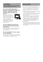
Страница 4: ...om an air conditioner for a long time it may cause a fire an electric shock or a malfunction of the TV Precautions If you use the TV installed on the Wall Mount Bracket for a long time the wall behind or above the TV may become discolored or the wallpaper may come unstuck depending on the material of the wall If the Wall Mount Bracket is removed after installing it on the wall the screw holes are ...

Страница 5: ...nual If you use substitute items the TV may fall and cause bodily injury to someone or damage to the TV To Sony Dealers Be sure to assemble the bracket properly following the instructed procedure explained in this instruction manual If any of the screws are loose or fall out the TV may fall and cause bodily injury to someone or damage to the TV Be sure to tighten the screws securely in the designa...

Страница 6: ...gram below Note If you intend to route the cables in a wall make a hole in the wall beforehand to make sure that the cables can be drawn into the wall The position for the cable hole is printed on the paper template and on page 15 Unit mm 100 100 100 300 Step 1 Checking the parts required for the installation 1 Prepare a Phillips screwdriver and the appropriate screws four or more M8 or equivalent...

Страница 7: ... installed on Reinforce the wall sufficiently if necessary Step 3 Installing the Plate Unit on the wall 1 Fix the Plate Unit to the wall using four or more M8 or equivalent screws not supplied Select at least four screw holes with the same mark shown in the diagram below and tighten the screws securely so that they will not come loose WARNING The screws securing the Wall Mount Bracket to the wall ...

Страница 8: ... angle step 1 and 2 below is not necessary Make sure that each stabiliser arm is screwed in securely 1 Remove the screws that are at the top and bottom center of the both stabiliser arms Then choose the notch corresponding to the desired angle 5 10 15 or 20 degrees and fit the stabiliser arm to it 2 Firmly secure each stabiliser arm using the screws removed in step 1 Notes Be sure to adjust the an...

Страница 9: ... to stumble over the mains lead or the TV as you may hurt yourself 1 Change the position of the woofer speaker 1 Loosen the four screws two on each side of the strut arms used to secure the woofer speaker in place about three turns 2 Slide the woofer speaker upward completely as shown below 3 Retighten the four screws loosened in step 1 to secure the woofer speaker Note If you fail to slide the wo...

Страница 10: ...V When you route the lead and the cable in the wall feed them through the hole you bored page 15 Hole for cable routing 2 Hitch the Mounting Rack on the hooks on the rear side of the TV Then slide the Mounting Rack and fix it using the supplied screws PSW5 L14 Note The woofer speaker connector is located on the lower right part of the Mounting Rack When sliding the Mounting Rack make sure that the...

Страница 11: ...er notches of the Mounting Rack 4 Firmly tighten all four upper and lower screws B6 L20 supplied on each side of the Mounting Rack 1 2 1 2 Mounting Rack Side view Plate Unit Mounting Rack with the TV Support brace Confirming the completion of the installation Check the following points Four upper hooks of the Mounting Rack are firmly hooked onto the two anchor bars of the Plate Unit The lead and t...

Страница 12: ... when carrying it Checking the operation of the woofer speaker This Wall Mount Bracket is equipped with a woofer speaker After installing the Mounting Rack with the TV onto the Plate Unit turn on the power switch of the TV and check if the woofer speaker is operating properly If the TV is not installed on the Mounting Rack properly no sound will be heard from the woofer speaker To Sony Dealers Not...

Страница 13: ...pinched and then plug in the mains lead WARNING Be sure two or more people do this work Be careful not to pinch your hands or fingers When connecting the external equipment to the TV after installation 1 Tilt the TV upward 1 Unplug the mains lead 2 Unfasten the two securing screws at the bottom of the Mounting Rack which were secured in step 4 of procedure 4 on page 11 3 Hold the bottom left and r...

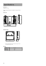
Страница 14: ... specifications are subject to change without notice PLATE UNIT SPEAKER Speaker unit 10 cm 2 Impedance 4 Ω Max power 50 W 670 420 520 505 MOUNTING RACK 480 79 85 5 44 When changing the position of the woofer speaker for installing a 50 inch TV 590 ø 90 ...

Страница 15: ...Hole for cable routing Slot hole Unit mm 670 610 455 406 420 65 5 ø 75 20 9 20 13 5 393 0 5 131 131 The wall that the TV will be installed on should be capable of supporting a weight of at least four times that of the TV CAUTION This Wall Mount Bracket is designed for use with the specified product above For other TVs refer to their operating instructions to check if this Wall Mount Bracket can be...

Страница 16: ...Printed in Japan ...

Отзывы: