


2
STR-K665P
Design and specifications are subject to change without notice.
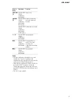
AM tuner section
Tuning range
With 10-kHz tuning scale: 530 - 1,710 kHz
3)
With 9-kHz tuning scale: 531 - 1,710 kHz
3)
Antenna
Loop antenna
Intermediate Frequency
450 kHz
3) You can change the AM tuning scale to 9 kHz or
10 kHz. After tuning in any AM station, turn off the
receiver. While holding down PRESET
or , press
?/1
. All preset stations will be
erased when you change the tuning scale. To reset
the scale to 10 kHz (or 9 kHz), repeat the procedure.
120 V AC, 60 Hz
General
Power requirements
160 W
Power consumption (during standby mode)
0.3 W
Dimensions (w/h/d) (Approx.)
430
×
145
×
301.5 mm
(17
×
5 6/8
×
11 7/8 inches)
including projecting parts
and controls
Mass (Approx.)
6.5 kg (14 lb 6 oz)
Power consumption
TABLE OF CONTENTS
1. GENERAL
···································································
4
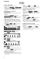
2. TEST MODE
······································································ 8
3. DIAGRAMS
3-1. Circuit Board Location ················································· 9
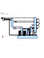
3-2. Block Diagrams – MAIN Section – ··························· 10
– DISPLAY/POWER Section – ································· 11
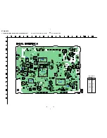
3-3. Printed Wiring Board
– DIGITAL Board (Side A) – ····································· 12
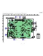
3-4. Printed Wiring Board
– DIGITAL Board (Side B) – ····································· 13
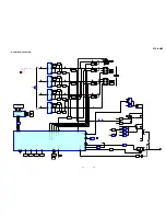
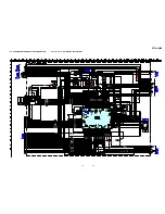
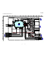
3-5. Schematic Diagram – DIGITAL Section (1/2) – ······· 14
3-6. Schematic Diagram – DIGITAL Section (2/2) – ······· 15
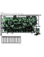
3-7. Printed Wiring Board – MAIN Section – ··················· 16
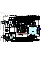
3-8. Schematic Diagram – MAIN Section (1/2) – ············· 17
3-9. Schematic Diagram – MAIN Section (2/2) – ············· 18
3-10. Printed Wiring Board – SUB WOOFER Board – ······ 19
3-11. Schematic Diagram – SUB WOOFER Board – ········· 19
3-12. Printed Wiring Board – POWER Section – ··············· 20
3-13. Schematic Diagram – POWER Section – ·················· 21
3-14. Printed Wiring Board – FRONT PANEL Section – ··· 22
3-15. Schematic Diagram – FRONT PANEL Section – ······ 23
3-16. IC Pin Function Descriptions ····································· 27
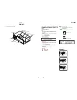
4. EXPLODED VIEWS
4-1. Front Panel Section ···················································· 29
4-2. Chassis Section ·························································· 30
5. ELECTRICAL PARTS LIST
····································· 31
Содержание STR-K665P - Receiver For Home Theater System
Страница 41: ...STR K665P MEMO ...


