


STR-DN1050
87
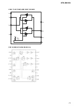
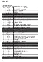
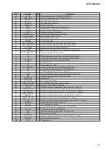
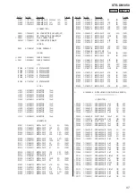
DIGITAL BOARD (10/12) IC3506 SII9575CTUC (HDMI RECEIVER)
Pin No.
Pin Name
I/O
Description
1 to 6
D14 to D19
I
Video data input terminal Not used
7
DE
I
Data enable signal input terminal Not used
8
VSYNC
I
Vertical sync signal input terminal Not used
9
HSYNC
I
Horizontal sync signal input terminal Not used
10
R0XC–
I
TMDS clock (negative) signal input from the HDMI IN 9 (VIDEO 2) connector
11
R0XC+
I
TMDS clock (positive) signal input from the HDMI IN 9 (VIDEO 2) connector
12
R0X0–
I
TMDS data (negative) input from the HDMI IN 9 (VIDEO 2) connector
13
R0X0+
I
TMDS data (positive) input from the HDMI IN 9 (VIDEO 2) connector
14
R0X1–
I
TMDS data (negative) input from the HDMI IN 9 (VIDEO 2) connector
15
R0X1+
I
TMDS data (positive) input from the HDMI IN 9 (VIDEO 2) connector
16
R0X2–
I
TMDS data (negative) input from the HDMI IN 9 (VIDEO 2) connector
17
R0X2+
I
TMDS data (positive) input from the HDMI IN 9 (VIDEO 2) connector
18
AVDD12
-
Power supply terminal (+1.2V)
19
AVDD33
-
Power supply terminal (+3.3V)
20
R1XC–
I
TMDS clock (negative) signal input from the HDMI input selector
21
R1XC+
I
TMDS clock (positive) signal input from the HDMI input selector
22
R1X0–
I
TMDS data (negative) input from the HDMI input selector
23
R1X0+
I
TMDS data (positive) input from the HDMI input selector
24
R1X1–
I
TMDS data (negative) input from the HDMI input selector
25
R1X1+
I
TMDS data (positive) input from the HDMI input selector
26
R1X2–
I
TMDS data (negative) input from the HDMI input selector
27
R1X2+
I
TMDS data (positive) input from the HDMI input selector
28
R2XC–
I
TMDS clock (negative) signal input from the HDMI input selector
29
R2XC+
I
TMDS clock (positive) signal input from the HDMI input selector
30
R2X0–
I
TMDS data (negative) input from the HDMI input selector
31
R2X0+
I
TMDS data (positive) input from the HDMI input selector
32
R2X1–
I
TMDS data (negative) input from the HDMI input selector
33
R2X1+
I
TMDS data (positive) input from the HDMI input selector
34
R2X2–
I
TMDS data (negative) input from the HDMI input selector
35
R2X2+
I
TMDS data (positive) input from the HDMI input selector
36
AVDD12
-
Power supply terminal (+1.2V)
37
CVDD12
-
Power supply terminal (+1.2V)
38
AVDD33
-
Power supply terminal (+3.3V)
39
R3XC–
I
TMDS clock (negative) signal input from the HDMI ASSIGNABLE (INPUT ONLY) IN 3
(SACD/CD) connector
40
R3XC+
I
TMDS clock (positive) signal input from the HDMI ASSIGNABLE (INPUT ONLY) IN 3
(SACD/CD) connector
41
R3X0–
I
TMDS data (negative) input from the HDMI ASSIGNABLE (INPUT ONLY) IN 3 (SA-CD/CD)
connector
42
R3X0+
I
TMDS data (positive) input from the HDMI ASSIGNABLE (INPUT ONLY) IN 3 (SA-CD/CD)
connector
43
R3X1–
I
TMDS data (negative) input from the HDMI ASSIGNABLE (INPUT ONLY) IN 3 (SA-CD/CD)
connector
44
R3X1+
I
TMDS data (positive) input from the HDMI ASSIGNABLE (INPUT ONLY) IN 3 (SA-CD/CD)
connector
45
R3X2–
I
TMDS data (negative) input from the HDMI ASSIGNABLE (INPUT ONLY) IN 3 (SA-CD/CD)
connector
46
R3X2+
I
TMDS data (positive) input from the HDMI ASSIGNABLE (INPUT ONLY) IN 3 (SA-CD/CD)
connector
47
R4XC–
I
TMDS clock (negative) signal input from the HDMI ASSIGNABLE (INPUT ONLY) IN 2 (BD)
connector
48
R4XC+
I
TMDS clock (positive) signal input from the HDMI ASSIGNABLE (INPUT ONLY) IN 2 (BD)
connector
49
R4X0–
I
TMDS data (negative) input from the HDMI ASSIGNABLE (INPUT ONLY) IN 2 (BD)
connector
50
R4X0+
I
TMDS data (positive) input from the HDMI ASSIGNABLE (INPUT ONLY) IN 2 (BD)
connector
51
R4X1–
I
TMDS data (negative) input from the HDMI ASSIGNABLE (INPUT ONLY) IN 2 (BD)
connector


