background image

79

GB

Ampl

ifier O

p

e

ration

5

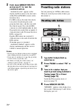
Press PRESET or 
PRESET TUNING – to select a 
preset number.

If you want to switch the memory page, 
press SHIFT on the remote.
If “MEMORY” goes out before you select 
the preset number, start again from step 4.

6

Press MEMORY/ENTER again.

The station is stored as the selected preset 
number. 
If “MEMORY” goes out before you press 
MEMORY/ENTER, start again from step 
4.

7

Repeat steps 2 to 6 to preset 
another station.

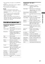
1

Turn INPUT SELECTOR to 
select tuner.

2

Press PRESET /– 
repeatedly to select the preset 
station you want.

Each time you press the button, you can 
select a preset station as follows:

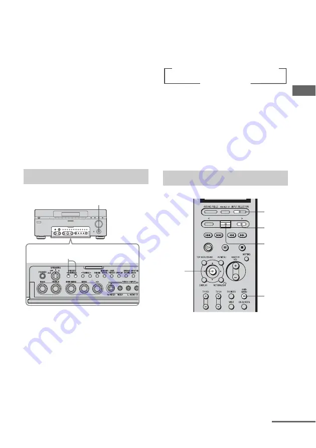
Using the remote

1

Press INPUT SELECTOR, then move the 
easy scroll key to select “TUNER” from the 
input list.

2

Move the easy scroll key to select the preset 
number you want, then press the key to enter 
the selection.

1

Press INPUT SELECTOR, then 
select “TUNER” from the input 
list.

You can also use INPUT SELECTOR on 
the receiver.

Tuning to preset stations

1

2

Naming preset stations

t

A1

y

A2

y

...

y

A0

y

B1

y

B2

y

...

y

B0

T

t

C0

y

...

y

C2

y

C1

T

1
2

4

5,6

3

continued

Содержание STR-DA7100ES - Fm Stereo/fm-am Receiver

Страница 1: ...reo FM AM Receiver Operating Instructions Owner s Record The model and serial numbers are located on the rear of the unit Record the serial number in the space provided below Refer to them whenever you call upon your Sony dealer regarding this product Model No Serial No STR DA7100ES ...

Страница 2: ...ular installation If this equipment does cause harmful interference to radio or television reception which can be determined by turning the equipment off and on the user is encouraged to try to correct the interference by one or more of the following measures Reorient or relocate the receiving antenna Increase the separation between the equipment and receiver Connect the equipment into an outlet o...

Страница 3: ...d shall be connected to the grounding system of the building as close to the point of cable entry as practical For customer in Canada CAUTION TO PREVENT ELECTRIC SHOCK MATCH WIDE BLADE OF PLUG TO WIDE SLOT FULLY INSERT Except for European model ENERGY STAR is a U S registered mark As an ENERGY STAR partner Sony Corporation has determined that this product meets the ENERGY STAR guidelines for energ...

Страница 4: ...Surround and the DTS Digital Surround System Manufactured under license from Dolby Laboratories Dolby Pro Logic Surround EX and the double D symbol are trademarks of Dolby Laboratories Manufactured under license from Digital Theater Systems Inc U S Pat No s 5 451 942 5 956 674 5 974 380 5 978 762 6 226 616 6 487 535 and other U S and world wide patents issued and pending DTS DTS ES Neo 6 and DTS 9...

Страница 5: ...5GB ...

Страница 6: ...ts COMPONENT VIDEO ASSIGN 63 Watching HDMI image from other inputs HDMI VIDEO ASSIGN 64 Storing the adjusted settings USER PRESET 65 Changing the menu setting 66 Changing the display 73 Using the Sleep Timer 74 Recording with other components 74 Listening to FM AM radio 76 Storing FM stations automatically AUTOBETICAL Models of area code CEL only 77 Presetting radio stations 78 Using the Radio Dat...

Страница 7: ...ally Macro Play 115 Setting remote control codes that are not stored in the commander 116 Clearing all the contents of the remote s memory 118 Other operations 118 Changing button assignments RM US106A only 120 Additional Information Menu list LEVEL SURR SET UP EQUALIZER TUNER SPEAKER SET UP CUSTOMIZE CIS STREAM INFO 122 Glossary 126 Technical terms 128 Precautions 130 Troubleshooting 131 Specific...

Страница 8: ...8GB Description and location of parts Getting Started Front panel Open the front cover ...

Страница 9: ...dio is decoded page 55 K Input lamps The lamp of the input source chosen lights up page 58 L Remote receiver Receives signals from remote commander M PHONES jack Connects to a headphone page 93 N SPEAKERS switch Switch to OFF A B A B of the front speakers page 52 O PRESET TUNING Press to select a preset number page 78 79 P TUNING Press to scan a station page 76 Q FM AM Press to select FM or AM pag...

Страница 10: ...NK jack page 29 58 Y VIDEO 3 INPUT To connect a video camera or TV game page 42 56 Z MENU MAIN MENU Adjust to select and enter menu and parameter settings page 62 65 80 97 98 102 wj TREBLE BASS Adjust the tonal quality bass treble level of each speaker page 105 Name Function ...

Страница 11: ...layback channel indicators L R C SL SR S SBL SBR SB The letters L C R etc indicate the channels being played back The boxes around the letters vary to show how the receiver downmixes the source sound based on the speaker settings lights up when the 9 1 channel speaker system is activated Front Left Front Right Center monaural Surround Left Surround Right Surround monaural or the surround component...

Страница 12: ...n INPUT MODE is set to COAXIAL FIXED page 60 Name Function J OPT Lights up when INPUT MODE is set to AUTO and the source signal is a digital signal being input through the OPTICAL jack or when INPUT MODE is set to OPTICAL FIXED page 60 K 96 24 Lights up when the receiver is decoding DTS 96 kHz 24 bit signals L ANALOG Lights up when INPUT MODE is set to AUTO and no digital signal being input throug...

Страница 13: ...n Pro Logic II or Pro Logic IIx Game decoding is activated page 91 wl PRO LOGIC II IIx Lights up when the receiver applies Pro Logic processing to 2 channel signals in order to output the center and surround channel signals This indicator also lights when the Pro Logic II or Pro Logic IIx Movie Music decoder is activated page 91 However this indicator does not light if both the center and surround...

Страница 14: ...r An image and the sound are output to TV or a projector page 39 i LINK jack Connects to Sony Super Audio CD player SCD XA9000ES page 29 B AUDIO INPUT OUTPUT section AUDIO IN OUT jack Connects to a tape deck or MD DAT player etc page 25 31 MULTI CHANNEL INPUT jack Connects to a Super Audio CD player or DVD player which has an analog audio jack for 7 1 channel or 5 1 channel sound page 25 28 PRE OU...

Страница 15: ... and amplifier tape deck etc which has a CONTROL A1II jack page 87 CTRL S Connects to a Sony TV and DVD player VCR etc which has a CONTROL S jack page 88 TRIGGER OUT Connectstointerlock ON OFF of the power supply of other 12V TRIGGER compliant components or the amplifier receiver of the 2nd 3rd zone page 82 IR REMOTE Connects to an IR repeater page 84 85 F COMPONENT VIDEO INPUT OUTPUT section COMP...

Страница 16: ...T SELECTOR D Depending on the component the above operation may not be possible or may operate differently than described C Display window The current status of the selected component or a list of selectable items appears here Note Characters other than letters of the alphabet or numbers may be displayed incorrectly on the remote even if they appear correctly on the display window on the receiver ...

Страница 17: ...DISPLAY Press to change the display of preset input components O Control key After pressing MAIN MENU J TOP MENU GUIDE P or AV MENU Q move the control key up down left or right to select the settings When you press TOP MENU GUIDE or AV MENU press this key to enter the selection P TOP MENU GUIDE Press to display the menu or on screen guide of the DVD player or satellite tuner on the TV screen Then ...

Страница 18: ...e the button assignments following the steps in Changing button assignments RM US106A only on page 120 D SHIFT When the tuner is selected press repeatedly to select a memory page for presetting radio stations or tuning to preset stations E MUTING Press to mute the sound F MASTER VOL Press to adjust the volume level for 2ND ZONE or 3RD ZONE output G RM SET UP indicator Lights up when data is being ...

Страница 19: ...ot be possible or may operate differently than described Name Function I Operation buttons The following table describes the function of the buttons J CH PRESET D SKIP Press repeatedly to select a preset station or channel When using a multi disc changer press to skip a disc Button s Function N Starts play Starts play on the front side of the cassette n Starts play on the reverse side of the casse...

Страница 20: ...ker R HSub woofer You can enjoy high fidelity reproduction of DVD software recorded sound in the Surround EX format if you connect one additional surround back speaker 6 1 channel or two surround back speakers 7 1 channel see Using the surround back decoding mode SURR BACK DECODING on page 95 Example of a 7 1 channel speaker system configuration AFront speaker L BFront speaker R CCenter speaker DS...

Страница 21: ... the center of the room is used as an axis for determining speaker placement you can enjoy excellent sound from anywhere in the room behind the central point When using the CINEMA STUDIO EX modes with a 9 1 channel system Be sure to set Virtual Speaker to OFF in SURR SET UP page 99 You can enjoy the surround effects of movies even without the use of virtual speakers since so many real speakers are...

Страница 22: ...g the IMPEDANCE SELECTOR To enjoy the best possible multi channel surround sound connect speakers with a nominal impedance of 8 ohms or higher to the FRONT CENTER SURROUND and SURROUND BACK terminals and set the IMPEDANCE SELECTOR to 8 Ω Refer to the operating instructions supplied with your speakers if you are not H G F B A D E C A B FRONT SPEAKERS B b IMPEDANCE SELECTORa AMonaural audio cord not...

Страница 23: ...s output from both the SPEAKERS jacks and the PRE OUT jacks For example if you want to connect just the front speakers to another amplifier connect that amplifier to the PRE OUT FRONT L and R jacks Connecting a 9 1 channel system Connect each speaker to the appropriate SURROUND SPEAKER L R jack when you set up a 9 1 speaker channel system You can use each part of speakers as surround speakers 1 L ...

Страница 24: ...This connection is used to output audio decoded by the component s internal multi channel decoder through this receiver c Model equipped only with AUDIO OUT L R jacks etc If you have Sony components with CONTROL A1II CONTROL S jacks See Operating Sony components on page 87 How to hook up your components Component to be connected Super Audio CD player CD player With digital audio outputa page 26 Wi...

Страница 25: ...he sound quality depends on the connecting jack Refer to the illustration that follows Select the connection according to the jacks of your components Audio input output jack to be connected High quality sound Digital Analog ...

Страница 26: ...dio CD player CD player and an MD DAT deck Component with digital audio input output jacks Super Audio CD player CD player MD DAT deck A B C D AOptical digital cord not supplied BAudio cord not supplied CCoaxial digital cord not supplied DAudio cord not supplied A ...

Страница 27: ... analog jack for recording in this case When connecting optical digital cords insert the plugs straight in until they click into place Do not bend or tie optical digital cords If you want to connect several digital components but cannot find an unused input See Listening to digital sound from other inputs DIGITAL ASSIGN page 61 Tips All the digital audio jacks are compatible with 32 kHz 44 1 kHz 4...

Страница 28: ...and Super Audio CD players do not have the SURR BACK jacks Set MULTI IN5 1 t 7 1 to NO in the CUSTOMIZE menu when the receiver and the player are connected using the 7 1 channel system The SURR BACK jacks of the MULTI CHANNEL INPUT are connected page 68 When SURR BACK SP is set to 2ND ZONE the input to the SURR BACK jacks is invalid page 49 Connecting components with multi channel output jacks DVD...

Страница 29: ...K jacks please refer to the Operating Instructions supplied with each component 1 Connecting one player to an i LINK jack 2 Connecting players to each i LINK jack 3 Connecting players to an i LINK jack Components with i LINK jacks i LINK cable supplied with a player not supplied with this receiver Player AUDIO i LINK cable supplied with a player not supplied with this receiver Player 2 AUDIO Playe...

Страница 30: ... used Use an i LINK cable of less than 1 5 meter 5 feet in length We do not guarantee playability when you connect a DVD player Super Audio CD CD player etc from another company with i LINK audio output jack If a metal object should fall into the i LINK jack short circuiting may occur and damage the components Be sure to insert the plug firmly to prevent malfunction For details about compatible si...

Страница 31: ...component such as tape deck turntable etc with analog jacks Note If your turntable has a ground wire connect it to the U SIGNAL GND terminal Components with analog audio jacks Super Audio CD player CD player Tape deck Turntable A MD DAT deck A AAudio cord not supplied A A ...

Страница 32: ...w to connect each component After hooking up all your components proceed to 4 Connecting the antennas page 43 If you have Sony components with CONTROL A1II CONTROL S jacks See Operating Sony components on page 87 How to hook up your components Component to be connected TV monitor page 35 DVD player page 37 38 Satellite tuner page 41 With HDMI jack page 39 VCR page 42 Video camera TV game etc page ...

Страница 33: ...signals You can output the video signal after connecting this receiver via the MONITOR OUT jack as shown in the illustration Video signals can be output as HDMI video component video and S video signals S video signals can be output as HDMI video component video and video signals Component video signals can be output as HDMI video S video and video signals You can switch the function for convertin...

Страница 34: ...for the images included in S video signals is effective only when S video input signals are output from the S video MONITOR OUT jack An aspect ratio of images may not be displayed correctly when video signals and component video signals are converted and are output from the S video MONITOR OUT jack Models of area code CEL only SECAM video signals are converted to PAL signals and output when VIDEO ...

Страница 35: ... a TV screen It is not necessary to connect all the cables Connect audio and video cords according to the jacks of your components Hooking up a TV monitor TV monitor A B C D E AAudio cord not supplied BOptical digital cord not supplied CComponent video cord not supplied DS video cord not supplied EVideo cord not supplied continued ...

Страница 36: ...the HDMI AUDIO setting if the sound is not output from the TV or you cannot play back multi channel software with HDMI connected page 70 Turn on the receiver when the video and audio of a playback component are being output to a TV via the receiver If the power supply of the receiver is not turned on neither video nor audio is transmitted Tip You can watch the selected input image when you connect...

Страница 37: ...cording to the jacks of your components 1 Connecting audio To output multi channel digital audio set the digital audio output setting on the DVD player Refer to the operating instructions supplied with the DVD player Hooking up a DVD player DVD player A B C AOptical digital cord not supplied BCoaxial digital cord not supplied CAudio cord not supplied continued ...

Страница 38: ...38GB 2 Connecting video DVD player A B C AComponent video cord not supplied BS video cord not supplied CVideo cord not supplied ...

Страница 39: ... AUDIO setting in the menu if the sound is not output from the TV speaker or you cannot play back multi channel software with HDMI connected page 70 To listen from the TV speaker set HDMI AUDIO to TV AMP in the CUSTOMIZE menu Components with HDMI jacks DVD player Satellite tuner TV monitor projector etc A A A AHDMI cable not supplied We recommend that you use a Sony HDMI cable continued ...

Страница 40: ... to the HDMI IN jack is not output from the REC OUT the 2ND ZONE jack or the 3RD ZONE jack of this receiver The multi stereo area audio signals of a Super Audio CD are not output Be sure to turn on the receiver when video and audio signals of a playback component are being output to a TV through this receiver Unless the power is on neither video nor audio signals will be transmitted Audio signals ...

Страница 41: ... the cables Connect audio and video cords according to the jacks of your components Connecting a satellite tuner Satellite tuner A B C D E F AAudio cord not supplied BOptical digital cord not supplied CCoaxial digital cord not supplied DComponent video cord not supplied ES video cord not supplied FVideo cord not supplied ...

Страница 42: ... how to connect a component which has analog jacks such as a VCR etc Components with analog video and audio jack VCR A To the VIDEO 3 INPUT jacks Front panel B Camcorder TV game B A AAudio video cord not supplied BS video cord not supplied ...

Страница 43: ... area code of this receiver Notes To prevent noise pickup keep the AM loop antenna away from the receiver and other components Be sure to fully extend the FM wire antenna After connecting the FM wire antenna keep it as horizontal as possible Do not use the U SIGNAL GND terminal for grounding the receiver FM wire antenna supplied AM loop antenna supplied ...

Страница 44: ...nent only while the receiver is turned on Make sure that the total power consumption of the component s connected to the receiver s AC OUTLET s does not exceed the wattage stated on the rear panel Do not connect high wattage electrical home appliances such as electric irons fans or TVs to this outlet This may cause a malfunction Before using the receiver for the first time initialize the receiver ...

Страница 45: ...batteries in the RM US106A remote control Observe the correct polarity when installing batteries Notes Do not leave the remote in an extremely hot or humid place Do not use a new battery with old ones Do not mix alkaline batteries and other kinds of batteries Do not expose the remote sensor of the receiver to direct sunlight or lighting apparatuses Doing so may cause a malfunction If you do not in...

Страница 46: ...3 To select the command mode for the main receiver Move the easy scroll key to select MAIN then press the key to enter the selection The MAIN list appears Move the easy scroll key to select AV SYSTEM 1 or AV SYSTEM 2 then press the key to enter the selection Tip The COMMAND MODE appears in the first line of the display only when the remote is turned on by pressing SOUND FIELD or INPUT SELECTOR To ...

Страница 47: ...er 3 Move the control key V v to select the menu item You can also use MENU on the receiver For more information see SPEAKER SET UP parameters page 48 Note Certain setup parameters may be dimmed in the display This means that the selected parameter is either unavailable or fixed and unchangeable due to sound field pages 89 94 or other settings 4 Move the control key B b to select the parameter You...

Страница 48: ...rol key to enter the main menu you want You can also use MAIN MENU on the receiver 5 Move the control key V v to select the menu item You can also use MENU on the receiver 6 Move the control key B b to select the parameter You can also use on the receiver 7 Press ON SCREEN The menu setting display disappears The initial settings are underlined x SP EASY SET UP Speaker easy setup YES You can set up...

Страница 49: ...ou connect a large speaker that will effectively reproduce bass frequencies select LARGE Normally select LARGE However if the front speakers are set to SMALL you cannot set the center speaker to LARGE SMALL If the sound is distorted or you feel a lack of surround effects when using multi channel surround sound select SMALL to activate the bass redirection circuitry and output the center channel ba...

Страница 50: ...ARGE If there is not enough bass you can use the equalizer to boost the bass levels For details on how to adjust the equalizer see page 104 x FRONT xx meter Front speaker distance Initial setting 3 0 meter 10 feet Lets you set the distance from your listening position to the front speakers A You can adjust this distance from 1 0 meter to 7 0 meters 3 to 23 feet in 0 1 meter 1 foot steps If both fr...

Страница 51: ...e surround speakers can not be set farther away from the listening position than the front speakers And they can be no more than 4 5 meter 15 feet closer This is because incorrect speaker placement is not conducive to the enjoyment of surround sound Please note that setting the speaker distance closer than the actual location of the speakers will cause a delay in the output of the sound from that ...

Страница 52: ...requency centered at 800 Hz 1 Turn on the receiver and TV 2 Press ON SCREEN Switch the input of the TV so that the setting menu is displayed on the TV screen connected to this receiver 3 Press MAIN MENU repeatedly to select LEVEL then press the control key Set to To select A The speakers connected to the FRONT SPEAKERS A terminals B The speakers connected to the FRONT SPEAKERS B terminals A B The ...

Страница 53: ... The menu setting display disappears For more precise adjustment You can output the test tone or sound source from two adjacent speakers to adjust their balance and level Set MENU EXPAND in the CUSTOMIZE menu to ON page 67 Then select the two speakers you want to adjust using PHASE NOISE or PHASE AUDIO on the LEVEL menu page 100 To operate on the receiver When you operate using the receiver be sur...

Страница 54: ... concert LIVE CONCERT STADIUM z You can listen to the sound that was recorded in the 2 channel format from all speakers multi channel Refer to page 90 for details 1 Turn on the Super Audio CD player CD player then set the disc in the tray 2 Turn on the receiver 3 Press INPUT SELECTOR then select SA CD CD by moving and pressing the easy scroll key You can also use INPUT SELECTOR on the receiver to ...

Страница 55: ...ODING lamp on the front panel lights up during playback Be sure this receiver is connected to the DVD player via a digital connection Be sure the digital audio output of the DVD player is set up properly 1 Turn on the TV and DVD player 2 Turn on the receiver 3 Press INPUT SELECTOR move the easy scroll key to select DVD from the list then press the key to enter the selection You can also use INPUT ...

Страница 56: ...e the easy scroll key to select VIDEO 3 from the list then press the key to enter the selection You can also use INPUT SELECTOR on this receiver to select VIDEO 3 When you connect a TV game to the VIDEO 3 INPUT jack on the front panel An example of the display 4 Switch the input of the TV so that an image of the TV game is displayed 5 Set up the TV game 6 Set the disc in the tray and play it back ...

Страница 57: ... the receiver 3 Press INPUT SELECTOR move the easy scroll key to select VIDEO 1 from the list then press the key to enter the selection You can also use INPUT SELECTOR on this receiver to select VIDEO 1 When you connect VCR to the VIDEO 1 jack An example of the display 4 Switch the input of the TV so that an image of the VCR is displayed 5 Play back the tape on the VCR 6 Adjust to a suitable volum...

Страница 58: ...the component for details Amplifier Operation 1 1 3 MUTING Selected input and display Components that can be played back VIDEO1 2 VCR etc connected to the VIDEO 1 or VIDEO 2 jack VIDEO3 Video camera and TV game etc connected to the VIDEO 3 jack DVD DVD player etc connected to DVD jack TV SAT Satellite tuner etc connected to the TV SAT jack TAPE Tape deck etc connected to the TAPE jack MD DAT MD DA...

Страница 59: ...use MASTER VOLUME on the receiver To mute the sound Press MUTING on the remote To cancel press MUTING on the remote again or turn MASTER VOLUME clockwise to raise the volume Even if you turn off the receiver the muting function works when you turn the receiver on again Switching the audio input mode INPUT MODE You can select the audio input mode by setting the audio input mode when you connect com...

Страница 60: ... 61 Some audio input modes may not be set up depending on the input A INPUT MODE button does not work when i LINK or HDMI input are selected Naming inputs You can enter a name of up to 8 characters for inputs and display it on the receiver s display This is convenient for attaching component names It will tell you which component is connected to which jack 1 Press INPUT SELECTOR to select an input...

Страница 61: ... of the name you entered You cannot change the Program Service PS name The name you entered will be overwritten by the Program Service PS name Listening to digital sound from other inputs DIGITAL ASSIGN You can assign digital audio input to other input which can be heard only analog sound VIDEO 1 2 IN etc For example when you connect two DVD players and the first DVD player is connected to the OPT...

Страница 62: ...he second DVD player will also become a digital sound through a COAXIAL jack The input you can assign varies for each audio input For details see Assignable inputs for digital audio input below Assignable inputs for digital audio input The initial setting is marked with an underscore Notes You cannot assign several digital audio inputs to the same input You cannot use the digital audio input as th...

Страница 63: ...lect the input VIDEO 1 in the example you want to assign as the component video input selected in step 4 You can also use on the receiver If an input is switched to VIDEO 1 the image from the DVD player will be a component image The input you can assign varies for each component video input For details see Assignable inputs for component video input below When you use the up convert function page ...

Страница 64: ...Move the control key V v to select an input You can also use MENU on the receiver 5 Move the control key B b to select the input you want to assign as an HDMI video input selected in step 4 You can also use on the receiver The input you can assign varies for each component video input For details see Assignable inputs for an HDMI video input Assignable inputs for an HDMI video input The initial se...

Страница 65: ...setting page 98 SCREEN DEPTH setting page 98 VIR SPEAKERS setting page 99 Tuner settings band frequency stereo mono setting preset number 2 Press MAIN MENU repeatedly to select CUSTOMIZE then press the control key You can also use MAIN MENU on the receiver to select CUSTOMIZE 3 Move the control key V v to select USER PRESET MEM You can also use MENU on the receiver 4 Move the control key B b to se...

Страница 66: ... USER PRESET stored in example 2 The INPUT MODE of TAPE is automatically set to ANALOG 2CH FIXED You cannot select AUTO 2CH or OPTICAL FIXED Changing the menu setting 1 Press MAIN MENU repeatedly to select CUSTOMIZE then press the control key You can also use MAIN MENU on the receiver to select CUSTOMIZE 2 Move the control key V v to select the menu item you want then press the key You can also us...

Страница 67: ...MS DEC PRIORITY Digital audio input decoding priority Lets you specify the input mode for the digital signal input to the DIGITAL IN and HDMI IN jacks AUTO Automatically switches the input mode between DTS Dolby Digital or PCM PCM PCM signals are given priority to prevent interruption when playback starts When set to AUTO and the sound from the digital audio jacks for a CD etc is interrupted when ...

Страница 68: ...INPUT jack as 7 1 channel signals NO Set to NO when the receiver and the player are connected using the 7 1 channel system The SURR BACK jack of the MULTI CHANNEL INPUT are connected DC PHASE L DC Phase Linearizer Lets you approximate the low frequency phase characteristics of a traditional analog amplifier OFF The bass is not enhanced LOW A STD A HIGH A LOW B STD B HIGH B The bandwidth range of t...

Страница 69: ...pending on the component and the sound source even if you set to ON i LINK VIDEO ASSIGN i LINK video input assignment You can assign video input to an i LINK input i LINK is selected as input and the i LINK component to set up needs to be recognized when you do this operation page 58 Move the control key V v to select an i LINK component Move the control key B b to select a number you want to memo...

Страница 70: ...e 64 HDMI AUDIO Let you set the audio output place of the playback component made HDMI connection with this receiver AMP The sound of the playback component is only output to speakers connected to this receiver Multi channel content can be played back as it is Note Sound is not output from the TV s speakers if HDMI AUDIO is set to AMP TV AMP The sound is output from TV s speaker and the speakers c...

Страница 71: ...LOR Video chroma level 4 You can adjust the chroma from 1 to 7 You cannot adjust the VIDEO COLOR when VIDEO CONVERT is set to OFF VIDEO HUE Video hue level 4 You can adjust the hue from 1 to 7 You cannot adjust the VIDEO HUE when VIDEO CONVERT is set to OFF COLOR SYSTEM OSD color system Models of area code CEL only Lets you select the color system to used NTSC The OSD color system is NTSC PAL The ...

Страница 72: ...rd is pulled out NAME IN Naming inputs Lets you set the name of inputs selected For details see Naming inputs on page 60 Menu item Parameter Explanation CUSTOMIZE menu setting Input signal MONITOR OUT VIDEO S VIDEO COMPONENT VIDEO VIDEO CONVERT ON PROGRESSIVE OUT ON VIDEO S VIDEO a a a 480p 576p COMPONENT VIDEO 480i 576i a a a 480p 576p COMPONENT VIDEO Other than 480i 576i X X X CUSTOMIZE menu set...

Страница 73: ...set station page 60 79 Index name does not appear when only blank spaces have been entered or it is the same as the input name You can check the input stream information a format channel etc of digital input signals The input stream information also appears for 4 seconds when the receiver detects any changes in the digital input signal 1 Press MAIN MENU repeatedly to select STREAM INFO You can als...

Страница 74: ...he remaining time appears on the display Recording with other components You can record on a MiniDisc or cassette tape using the receiver See the operating instructions supplied with your cassette deck or MD deck 1 Press INPUT SELECTOR then select the playback component by moving and pressing the easy scroll key You can also use INPUT SELECTOR on the receiver 2 Prepare the playback component for p...

Страница 75: ...INPUT SELECTOR then select the playback component by moving and pressing the easy scroll key You can also use INPUT SELECTOR on the receiver 2 Prepare the component for playing For example insert the video tape you want to copy into the VCR 3 Prepare the recording component Insert a blank video tape etc into the recording component VIDEO 1 or VIDEO 2 for recording 4 Start recording on the recordin...

Страница 76: ...gh press TUNING to scan from high to low The receiver stops scanning whenever a station is received In case of poor FM stereo reception If the FM stereo reception is poor and STEREO flashes on the display select monaural audio so that the sound will be less distorted 1 Turn MAIN MENU to select TUNER 2 Turn MENU to select FM MODE 3 Turn to select MONO The FM reception switches to monaural Enter the...

Страница 77: ... 1 350 kHz Select 1 b 3 b 5 b 0 You do not have to enter the last 0 when the tuning scale is set to 10 kHz If you have tuned in an AM station adjust the direction of the AM loop antenna for optimum reception If you cannot tune in a station and the entered numbers flash Make sure you have entered the right frequency If not repeat step 4 If the entered numbers still flash the frequency is not used i...

Страница 78: ... any button on the receiver or supplied remote during autobetical operation except 1 If you move to another area repeat this procedure to store stations in your new area For details on tuning the stored stations see Tuning to preset stations on page 79 If you move the antenna after storing stations with this procedure the stored settings may no longer be valid If this happens repeat this procedure...

Страница 79: ...r station 1 Turn INPUT SELECTOR to select tuner 2 Press PRESET TUNING repeatedly to select the preset station you want Each time you press the button you can select a preset station as follows Using the remote 1 Press INPUT SELECTOR then move the easy scroll key to select TUNER from the input list 2 Move the easy scroll key to select the preset number you want then press the key to enter the selec...

Страница 80: ...ional information along with the regular program signal You can display RDS information Simply select a station on the FM band using direct tuning page 76 automatic tuning page 76 or preset tuning page 78 When you tune in a station that provides RDS services the RDS indicator lights up and the program service name appears on the display Note RDS may not work properly if the station you tuned to is...

Страница 81: ...ience Programs about the natural sciences and technology Varied Speech Other types of programs such as celebrity interviews panel games and comedy Pop Music Popular music programs Rock Music Rock music programs M o R Music Easy Listening Light Classics M Instrumental vocal and choral music Serious Classics Performances of major orchestras chamber music opera etc Other Music Music that does not fit...

Страница 82: ...r 2nd zone only analog audio signals for 3rd zone you want to output in the 2nd zone or 3rd zone except PHONO MULTI CHANNEL INPUT i LINK and HDMI When you select SOURCE the signals of the current input are output Notes Connect video signals to 2ND ZONE using the VIDEO jack Connect audio signals to 2ND ZONE or 3RD ZONE using the AUDIO L R jack Tips Only signals from components connected to the anal...

Страница 83: ...main receiver or the receiver in each zone is turned on INPUT for 12V TRIG MAIN only Lets you turn on output of 12V triggers when the main receiver is turned on depending on the setting of each input See To set the 12V trigger setting for each input MAIN for 12V TRIG 2ND and 12V TRIG 3RD only Lets you link 2nd or 3rd zone trigger operation to the main receiver To set the 12V trigger setting for ea...

Страница 84: ... in main room and Sony receiver in the 2nd or 3rd zone from the 2nd or 3rd zone Use the RM US106A remote for the operation Switching the output source for the 2ND or 3RD ZONE OUT jacks Switching the Sony receiver s power on or off in the 2nd or 3rd zone Adjusting the volume of the Sony receiver in the 2nd or 3rd zone 1 2nd zone connections 1 2ND ZONE VIDEO AUDIO OUT jack Main room 2nd zone VIDEO O...

Страница 85: ...onitor A VIDEO OUT B D STR DA7100ES D SURROUND BACK SPEAKERS AAudio component BVideo component CIR repeater not supplied DSpeaker RM US106A C A AUDIO OUT B C E E D RM US106A STR DA7100ES C Main room 3rd zone AAudio component BVideo component CIR repeater not supplied DSony s Amplifier Receiver ESpeaker continued ...

Страница 86: ... 49 2 Adjust the volume using MASTER VOL on the remote The initial setting of the volume is dB no sound output Example of controlling an amplifier in the 2nd room Tips Even when this receiver is turned off the receiver in the 2nd zone or 3rd zone remains turned on To turn off all receivers press 1 and AV 1 on the RM AAE003 remote at the same time SYSTEM STANDBY Only signals from components connect...

Страница 87: ...s with CONTROL A1II jacks the number of functions that can be controlled may be limited depending on the component For detailed information refer to the operating instructions supplied with the component s If you have a Sony CD changer with a COMMAND MODE selector If your CD changer s COMMAND MODE selector can be set to CD 1 CD 2 or CD 3 be sure to set the command mode to CD 1 and connect the chan...

Страница 88: ...ack on the receiver to the appropriate CONTROL S jack on the respective component Refer to the operating instructions supplied with your TV satellite tuner monitor VCR etc for details If you connect the CTRL S OUT jack on another component to the CTRL S IN jack on this unit Example The remote sensor on the CTRL S OUT component receives remote codes the same way as the remote sensor on this unit Th...

Страница 89: ...fer when there is no L F E signal which is a low pass sound effect output from a sub woofer to a 2 channel signal Detecting the type of audio signal automatically AUTO FORMAT DIRECT The Auto Format Direct A F D mode allows you to listen to higher fidelity sound and select the decoding mode for listening to a 2 channel stereo sound as multi channel sound In this mode the receiver automatically dete...

Страница 90: ...g for 2 channel audio sources 1 Press SOUND FIELD The sound field list appears 2 Move the easy scroll key to select an A F D mode then press the key to enter the selection You can also use A F D on the receiver Enjoying stereo sound in multi channel 1 2 ...

Страница 91: ... CDs A F D PRO LOGIC II GAME PRO LOGIC II GAME 5 channel Performs Dolby Pro Logic II Game mode decoding Dolby Pro Logic IIx A F D PRO LOGIC IIx MOVIE PRO LOGIC IIx MOVIE 7 channel Performs Dolby Pro Logic IIx Movie mode decoding This setting is ideal for movies encoded in Dolby Surround In addition this mode can reproduce sound in 7 1 channel for watching videos of overdubbed or old movies A F D P...

Страница 92: ...Dolby prologic IIx multi channel sound being encoded is output Selecting a sound field You can take advantage of surround sound simply by selecting one of the receiver s preprogrammed sound fields They bring the exciting and powerful sound of movie theaters and concert halls into your home Press MOVIE repeatedly to select the sound field you want The sound field list appears Types of sound field a...

Страница 93: ...ed the Digital Cinema Sound lamp lights up Press MUSIC repeatedly to select the sound field you want The sound field list appears Types of sound field available x D CONCERT HALL A Uses 3D sound imaging to reproduce the sound characteristics of a concert hall which simulates a large sound stage produced by reflectivity x D CONCERT HALL B Uses 3D sound imaging to reproduce the sound characteristics ...

Страница 94: ...a signal higher than 48kHz To turn off the surround effect for MOVIE MUSIC Move the easy scroll key to select either A F D AUTO or 2CH STEREO in the sound field list on the display This function allows you to retain a theater like environment at low volume levels This function can be used with other sound fields When watching a movie late at night you will be able to hear the dialog clearly even a...

Страница 95: ...nel decoding in the input stream page 96 x OFF Surround back decoding is not performed a A 6 1 channel decode flag is information recorded in software like DVDs b A Dolby Digital DVD that includes a Surround EX flag The Dolby Corporation web page can help you distinguish Surround EX films c Software encoded with a flag to denote it has both DTS ES Matrix and 5 1 channel signals d Software encoded ...

Страница 96: ...e speaker setting is 7 1 channel when you select Dolby PLIIx MS under the following conditions a Dolby Digital Surround EX signal is input the SB DECODING is set to AUTO Input Stream indicator When AUTO FORMAT DIRECT mode is selected while the surround back decoder is activated the current decoding process is displayed after the input stream is displayed a few seconds x When the decoder conforms t...

Страница 97: ...repeatedly to select SURR SET UP then press the control key You can also use MAIN MENU on the receiver to select SURR SET UP 3 Move the control key V v to select the parameter you want then press the key You can also use MENU on the receiver For details see SURR SET UP menu parameters below Input stream After a few seconds Current decoding process DOLBY DIGITAL 3 2 1 k DOLBY D 3 2 1 PLIIx DOLBY DI...

Страница 98: ...y Pro Logic II decoding to the L R speakers x DIMENSION F_ _S Dimension control Initial setting midpoint 0 Lets you perform further adjustments for Dolby Pro Logic II and IIx Music mode decoding You can set this parameter only when A F D mode is set to PRO LOGIC II MUSIC or PRO LOGIC IIx MUSIC page 91 You can adjust the difference between the front channels and the surround channels x PANORAMA MOD...

Страница 99: ...to select the parameter you want You can also use MENU on the receiver For details see LEVEL menu parameters 4 While monitoring the sound adjust the selected parameter by moving control key B b You can also use to adjust the selected parameter 5 Repeat steps 3 and 4 to adjust the other parameters LEVEL menu parameters x TEST TONE Test Tone Initial setting OFF Lets you output the test tone sequenti...

Страница 100: ...LTI CHANNEL INPUT jacks The sub woofer level from DVD players is 10 dB lower than that of Super Audio CD players Only when the surround back speakers are set to SINGLE on the SPEAKER SET UP menu page 49 Only when the surround back speakers are set to DUAL on the SPEAKER SET UP menu page 49 Note When one of the following sound fields is selected no sound is output from the sub woofer if all the spe...

Страница 101: ...e compressor lets you compress the dynamic range of the soundtrack based on the dynamic range information included in the Dolby Digital signal STD is the standard setting but it only enacts light compression Therefore we recommend using the MAX setting This greatly compresses the dynamic range and lets you view movies late at night at low volumes Unlike analog limiters the levels are predetermined...

Страница 102: ...You can also use MENU on the receiver For details see SPEAKER SET UP parameters on page 48 3 Move the control key B b to select the parameter you want You can also use on the receiver 4 Repeat steps 2 and 3 to adjust the other parameters x DISTANCE UNIT Distance unit Lets you select the unit of measure for setting distances feet default for models of area code UC The distance is displayed in feet ...

Страница 103: ...surround speakers positioned at a rather wide angle However if the speakers are pointing toward the listener from the immediate left and right of the listening position the surround effects become unclear unless set to SIDE Nevertheless each listening environment has many variables like wall reflections and you may obtain better results using BEHD if your speakers are located high above the listen...

Страница 104: ...receiver 5 Move the control key V v to select the parameter You can also use MENU on the receiver For details see EQUALIZER menu parameters below 6 While monitoring the sound adjust the selected parameter by moving control key B b You can also use to adjust the selected parameter 7 Repeat steps 5 and 6 to adjust the other items EQUALIZER menu parameters x EQ PRESET Preset equalizer selection Lets ...

Страница 105: ...tting For details see Clearing stored equalizer settings Tip You can adjust the front speaker bass and treble level with BASS control and TREBLE control on the receiver To apply the stored equalizer 1 Perform step1 to 3 in Adjusting the equalizer on page 104 2 Move the control key B b to select EQ PRESET 1 5 You can also use on the receiver To turn off the equalizer Select EQ BANK OFF in step 4 in...

Страница 106: ... are given from page 58 Some items have sub lists that appear when you press page 110 Using the Remote Deck A B status information 2nd zone input list 3rd zone input list Press page 58 Press When COMMAND MODE is set to 2ND ZONE only the 2nd zone list appears When COMMAND MODE is set to 3RD ZONE only the 3rd zone list appears RECEIVER menu ...

Страница 107: ...he Remote Sound field list IR SET list CATEGORY list MAKER list BUTTON list MACRO 1 2 list PROGRAM list CATEGORY list COMMON list LEARNING list BUTTON list MAKER list FUNCTION list TV INPUT list Press Press page 92 ...

Страница 108: ...onent is actually connected to the jacks on the receiver If a component is connected to jacks for which they are not originally meant you can modify the category indication to match the component For details see Programming the remote on page 113 You can set the remote to automatically turn on a component when it is selected from the function list For details see Using the auto power function on p...

Страница 109: ...o change the contents of the input list to match your particular components see Programming the remote on page 113 Table of buttons used to control each component Component Button VCR TV LD player DVD player VideoCD player CD player MD deck Tape deck A and B DAT deck Tuner Cable box Satellite tuner Projector AV 1 z z z z z z z z z z H z z z z z z z z X z z z z z z z z x z z z z z z z z z z z z z z...

Страница 110: ... playback speed REC Starts recording COUNTER REMAIN Displays the playing or remaining time TV CH Selects preset channels CH MUTING Mutes the sound VOL Raises the volume VOL Lowers the volume JUMP Toggles between the previous and current channels TV VIDEO Changes the input mode of the TV MPX DUAL Changes the audio setting WIDE Selects the wide picture mode a P IN P Activates the picture in picture ...

Страница 111: ...ges the time information DISC SKIP Selects a disc DISC SKIP Component Item s Function MD deck DISC SKIP Selects a disc DISC SKIP TIME Changes the time information CONTINUE Selects Continuous Play SHUFFLE Selects Shuffle Play PROGRAM Selects Program Play REPEAT Selects Repeat Play MENU NO Selects an editing operation or cancels editing YES Performs an editing operation CLEAR Erases a track in the p...

Страница 112: ...e Station Index Satellite tuner BST CH Selects preset channels CH Selects the channel of eleven or higher MAIN SUB Switched the main or sub language TV RADIO Switches the TV or radio input Component Item s Function Projector POWER ON Turns on the projector POWER OFF Turns off the projector INPUT A Switches to the input from INPUT A jacks INPUT B Switches to the input from INPUT B jacks INPUT VIDEO...

Страница 113: ...non Sony components and also Sony components that the remote is normally unable to control The procedure below uses as an example a case in which an Aiwa VCR is connected to the VIDEO 2 jacks on the receiver Before you begin note that You cannot change the settings of PHONO The remote can control only components that accept infrared wireless control signals Be sure to turn on the receiver and poin...

Страница 114: ...ve the easy scroll key to select the maker of the component Aiwa for example then press the key to enter the selection To cancel programming Move the easy scroll key to select Exit or Cancel during any step then press the key to enter the selection To use a programmed component Press the programmed button to activate the input you want Tip You can freely assign any component to USER1 and USER2 ite...

Страница 115: ...to enter the selection The category list appears 5 Move the easy scroll key to select the component category VCR for example then press the key to enter the selection The maker list appears 6 Move the easy scroll key to select the maker then press the key to enter the selection The function list appears 7 Move the easy scroll key to select the IR code for the operation you want to perform then pre...

Страница 116: ...the macro play sequence before it is complete AV 1 1 SYSTEM STANDBY SOUND FIELD INPUT SELECTOR RM SET UP When the Macro Play function does not work properly set WAIT TIME between each operation Setting remote control codes that are not stored in the commander When a remote control code is not one of the presets stored in the commander it is possible for the commander to learn the code using the Le...

Страница 117: ... easy scroll key to select Clear then press the key to enter the selection Clear appears 2 Move the easy scroll key to select Yes then press the key to enter the selection Cleared appears Notes The symbols that are displayed in front of the button name indicate the following x already learned pre programmed In step 4 learned buttons can be selected directly If you press the button you want to use ...

Страница 118: ... are cleared Other operations You can set the remote to display only the inputs you use in the input list 1 Press RM SET UP The set up list appears 2 Move the easy scroll key to select INPUT LIST then press the key to enter the selection The INPUT LIST list appears A in front of the input name means that the input is displayed in the input list 3 Move the easy scroll key to select an input that wi...

Страница 119: ...MPO1 or 2 Notes Switching to VIDEO1 6 input may not be automatic on all Sony TVs This is because some TVs cannot receive remote control codes immediately after being turned on If you select Off in step 3 the TV input does not switch Each time you press a button on the remote the backlight turns on If you follow the procedure below to turn off the backlight you can make the batteries last longer 1 ...

Страница 120: ...he factory settings of the input buttons to suit the components in your system For example if you connect an LD player to the VIDEO 2 jacks on the receiver you can set the VIDEO 2 button on this remote to control the LD player Note however that the settings of the TUNER button cannot be changed 1 Press RM SET UP for more than 2 seconds The indicator lights up 2 Press the input button of which you ...

Страница 121: ...its the button assignment mode Start again from step 1 In step 3 if you press the same button more than the possible number of categories that can be selected only the last category is registered for the new assignment Valid buttons and the corresponding categories To clear all remote button assignments Hold down RM SET UP then press 1 The remote is reset to its factory settings Corresponding cate...

Страница 122: ...to 10 0dB 0 5dB step 0dB SURR BACK xxx x dB 20 0dB to 10 0dB 0 5dB step 0dB SURR BACK L xxx x dB 20 0dB to 10 0dB 0 5dB step 0dB SURR BACK R xxx x dB 20 0dB to 10 0dB 0 5dB step 0dB SUB WOOFER xxx x dB 20 0dB to 10 0dB 0 5dB step 0dB MULTI CH SW xxx 0dB 10 0dB 0dB D RANGE COMP xxx OFF STD MAX OFF SURR SET UP C WIDTH L C R 8 step 3 page 98 99 DIMENSION F S 7 step Center PANORAMA MODE _ _ _ OFF ON O...

Страница 123: ...DUAL DUAL FRONT x xmeter 1 0m to 7 0m 0 1m step 3 0 meter CENTER x xmeter 1 0m to 7 0m 0 1m step 3 0 meter SURROUND x xmeter 1 0m to 7 0m 0 1m step 3 0 meter SURR BACK x xmeter 1 0m to 7 0m 0 1m step 3 0 meter SUB WOOFER x xmeter 1 0m to 7 0m 0 1m step 3 0 meter DISTANCE UNIT xxx meter feet meter page 102 103 SP POSI xxx SIDE LOW SIDE HIGH BEHD LOW BEHD HIGH SIDE LOW SP CROSSOVER xxxHz 40Hz to 200...

Страница 124: ...NONE VIDEO1 VIDEO2 VIDEO3 DVD TAPE MD DAT SA CD CD DVD TV SAT NONE VIDEO1 VIDEO2 VIDEO3 TV SAT TAPE MD DAT SA CD CD TV SAT HDMI VIDEO ASSIGN HDMI 1 NONE VIDEO1 VIDEO2 VIDEO3 DVD TV SAT TAPE MD DAT SA CD CD NONE HDMI 2 NONE VIDEO1 VIDEO2 VIDEO3 DVD TV SAT TAPE MD DAT SA CD CD NONE HDMI AUDIO AMP TV AMP AMP HDMI POWER AUTO EVER ON AUTO VIDEO CONVERT ON OFF ON PROGRESSIVE OUT ON OFF OFF VIDEO BRIGHTN...

Страница 125: ...IDEO3 DVD TV SAT TAPE MD DAT SA CD CD TUNER SOURCE page 82 3RD ZONE SOURCE VIDEO1 VIDEO2 VIDEO3 DVD TV SAT TAPE MD DAT SA CD CD TUNER SOURCE INSTALLER MODE OFF ON OFF 12V TRIG MAIN OFF CTRL ZONE INPUT OFF 12V TRIG 2ND OFF CTRL ZONE MAIN OFF 12V TRIG 3RD OFF CTRL ZONE MAIN OFF STREAM INFO STREAM xxxxxx page 73 Menu Item Parameter Initial setting Refer page ...

Страница 126: ...round back information is matrixed into regular left and right surround channels so that the sound can be reproduced in 6 1ch Active scenes especially are recreated with a more dynamic and realistic sound field x Dolby Pro Logic II This technology converts 2ch stereo recorded audio into 5 1ch for playback There is a MOVIE mode for movies and MUSIC mode for stereo sources such as music Old movies e...

Страница 127: ...rals This is a new interface that enables a simple connection with a single cable between a player and an amplifier 5 1ch information is transmitted digitally so that clear sound reproduction is possible x Input stream A digital input signal that includes additional information about the format or channel such as Dolby Digital 5 1 or DTS 5 1 data etc x Interlace A scanning method which completes a...

Страница 128: ...produces treble attenuation fullness and depth of sound usually created in a theater using sound emission from behind the screen This is then added to the front and center channels Cinema Studio Reverberation reproduces the sound characteristics of state of the art dubbing theaters and recording studios including Sony Pictures Entertainment s dubbing studios There are three modes A B C available a...

Страница 129: ... concert hall x Pulse Height Volume Pulse Height Volume one feature of the S Master PRO technology adjusts the sound volume by controlling the pulse height This method loses no information and reproduces higher quality sound than adjusting the sound volume by digital processing x S Master This receiver is equipped with an S Master full digital amplifier a unique digital amplifier developed by Sony...

Страница 130: ... continuously use this unit at a large volume the cabinet temperature of the top side and bottom rises considerably To avoid burning yourself do not touch the cabinet On placement Place the receiver in a location with adequate ventilation to prevent heat buildup and prolong the life of the receiver Do not place the receiver near heat sources or in a place subject to direct sunlight excessive dust ...

Страница 131: ...h is not outputting any sound Make sure you have not connected only the L or R jack to a monaural component Use a monaural stereo cable not supplied and connect it to both the L and R jacks However there will be no sound from the center speaker when a sound field PRO LOGIC etc is selected When the center speaker is set to NO sound is output only from the front L R speakers There is no sound or onl...

Страница 132: ... the LEVEL menu There is severe hum or noise Check that the speakers and components are connected securely Check that the connecting cords are away from a transformer or motor and at least 3 m 10 feet away from a TV set or fluorescent light Move your TV away from the audio components Make sure you have grounded the U SIGNAL GND terminal only when a turntable is connected The plugs and jacks are di...

Страница 133: ...Use direct tuning Make sure you set the tuning interval correctly when tuning in AM stations with direct tuning No stations have been preset or the preset stations have been cleared when tuning by scanning preset stations Preset the stations page 78 Press DISPLAY so that the frequency appears on the display RDS does not work Make sure that you re tuned to an FM RDS station Select a stronger FM sta...

Страница 134: ... between the remote and the receiver Replace all the batteries in the remote with new ones if they are weak Check if the command modes of the receiver and the remote are the same If the command mode of the receiver and the remote are different you cannot operate the receiver with the remote page 46 Make sure you select the correct input on the remote When 2ND ZONE or 3RD ZONE appears or when the s...

Страница 135: ...t the player again LOOP CONNECT CHECK CODE 74 i LINK connection is caught in a loop Check the connection page 29 Reference sections for clearing the memory Specifications AUDIO POWER SPECIFICATIONS POWER OUTPUT AND TOTAL HARMONIC DISTORTION Models of area code UC only With 8 ohm loads both channels driven from 20 20 000 Hz rated 170 watts per channel minimum RMS power with no more than 0 15 total ...

Страница 136: ...stortion at 1 kHz Mono 0 3 Stereo 0 5 Separation 45 dB at 1 kHz Frequency response 30 Hz 15 kHz 0 5 2 dB Selectivity 60 dB at 400 kHz AM tuner section Tuning range Models of area code UC 530 1 710 kHz3 With 10 kHz tuning scale 531 1 710 kHz3 With 9 kHz tuning scale Area code Power requirements UC 120 V AC 60 Hz TW 110 V AC 60 Hz CEL 230 V AC 50 60 Hz KR 220 V AC 60 Hz CN 220 V AC 50 Hz PHONO RIAA ...

Страница 137: ...00 Maximum data transmission speed 200 Mbps Transmission protocol A M transmission protocol Format input Super Audio CD DSD PLAIN 2 channel linear PCM IEC 60958 3 Sampling frequency 44 1 kHz Conforms to the copy protection technology of DTLA Revision 1 3 General Power requirements Power consumption Power consumption during standby mode 1 W AC outlets Dimensions 430 175 470 mm 17 7 18 5 8 in includ...

Страница 138: ...nable input signal 34 AUTO FORMAT DIRECT 89 AUTOBETICAL 77 C CD CD player 27 Playback 54 Center frequency 52 Changing the display 73 COMPONENT VIDEO ASSIGN 63 CONTROL A1II 87 CONTROL S 88 Conversion 33 D DCS 92 93 DIGITAL ASSIGN 61 Display window 11 Dolby 91 95 97 Downmix 89 DTS 95 97 DVD hooking up 37 38 Playback 55 E Error messages 134 H HDMI connecting 39 HDMI AUDIO 70 HDMI POWER 71 HDMI VIDEO ...

Страница 139: ... component 109 programming 113 RM AAE003 16 RM US106A 18 SUB menu 110 Resetting 135 S Satellite tuner 41 SB DEC MODE 96 Sleep Timer 74 Sound fields customizing 97 101 resetting 101 selecting 92 Speakers Connecting 22 Levels and balance 52 53 Set the distance 50 Setup 47 52 SPEAKERS switch 52 Storing the adjusted settings 65 STREAM INFO 73 Super Audio CD 27 Connecting 28 Playback 54 SURR BACK DECOD...

Отзывы: