STR-DA5400ES
155
Pin No.
Pin Name
I/O
Description
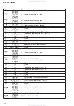
67 to 72
SRAM A2 to SRAM A7
O
Address signal output to the S-RAM
73
+3.3V
-
Power supply terminal (+3.3V)
74
GND
-
Ground terminal
75 to 83
SRAM A8 to SRAM A16
O
Address signal output to the S-RAM
84 to 87
NO USE
-
Not used
88
GND
-
Ground terminal
89
+3.3V
-
Power supply terminal (+3.3V)
90, 91
NO USE
-
Not used
92
NON_LPCM
O
Non-LPCM setting signal output terminal "L": LPCM
93
1444_HPD1
O
Hot plug detection control signal output to the HDMI input selector
94
1444_OEB1
O
Output enable signal output to the HDMI input selector
95, 96
+5V_SELA, +5V_SELB
O
HDMI +5V power input selection signal output terminal
97
NO USE
-
Not used
98
AUDIO MUTE
REQ
O
Audio muting signal output terminal
99 to 101
1444_SELA1 to
1444_SELC1
O
HDMI input selection signal output to the HDMI input selector
102
1444_HPD2
O
Hot plug detection control signal output to the HDMI input selector
103
NO USE
-
Not used
104
1444_OEB25
O
Output enable signal output to the HDMI input selector
105, 106
NO USE
-
Not used
107 to 109
1444_SELA2 to
1444_SELC2
O
HDMI input selection signal output to the HDMI input selector
110
MAIN_FARO_WAKE
O
Wake-up signal output to the video processor1
111
FRONT_HPD
O
Not used
112
EDIO2_SEL
O
Not used
113
2nd_FARO_WAKE
O
Wake-up signal output to the video processor2
114
GND
-
Ground terminal
115, 116
+3.3V
-
Power supply terminal (+3.3V)
117
UC3V_SDA
I/O
I2C data bus with the EEPROM, HDMI receiver, HDMI transmitter and D/A converter (for
video section)
118
UC3V_SCL
O
I2C clock signal output to the EEPROM, HDMI receiver, HDMI transmitter and D/A converter
(for video section)
119
YAMAHA_INT_N
I
Interrupt signal input from the OSD controller
120
NO USE
-
Not used
121
RX_INT
I
Interrupt signal input from the HDMI receiver
122
NO USE
-
Not used
123
TX_INT1
I
Interrupt signal input from the HDMI transmitter
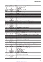
-
Not used
I
Power detection signal input from the video processor1
O
Reset signal output to the video processor1 and
fl
ash memory "L": reset
-
Mode setting terminal Fixed at "L" in this set
I
Mode setting signal input from the system controller
-
Mode setting terminal Fixed at "L" in this set
I
Reset signal input from the system controller "L": reset
-
Ground terminal
133
+5V
-
Power supply terminal (+3.3V)
134
Flash Update RX
I
Serial data input terminal
135
Flash Update TX
O
Serial data output terminal
136
ENDFLAG
O
End
fl
ag output to the system controller
137, 138
NO USE
-
Not used
139
MAIN UCOM
UART BUSY
I
Busy signal input from the system controller
140
Faroudjia UCOM
UART RX
I
Serial data input from the video processor1
141
Faroudjia UCOM
UART TX
O
Serial data output to the video processor1
www. xiaoyu163. com
QQ 376315150
9
9
2
8
9
4
2
9
8
TEL 13942296513
9
9
2
8
9
4
2
9
8
0
5
1
5
1
3
6
7
3
Q
Q
TEL 13942296513 QQ 376315150 892498299
TEL 13942296513 QQ 376315150 892498299


