STR-DA5400ES
154
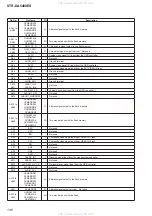
D VIDEO BOARD IC3610 MB91F467RAPMC-GE1 (VIDEO SYSTEM CONTROLLER)
Pin No.
Pin Name
I/O
Description
1
GND
-
Ground terminal
2
STOP IN
I
AC off detection signal input terminal "L": AC off
3
DAC CLOCK SEL
O
Clock control signal output to the frequency multiplier for D/A converter (for video section)
4
MAIN UCOM SDA
I/O
Two-way I2C data bus with the system controller
5
MAIN UCOM SCL
I/O
Two-way I2C clock bus with the system controller
6
DAC SDA
I/O
Two-way I2C data bus with the D/A converter (for video section)
7
DAC SCL
O
I2C clock signal output to the D/A converter (for video section)
8, 9
EDID_SEL0,
EDID_SEL1
O
Input data selection signal output terminal
10
NO USE
-
Not used
11, 12
+3.3V
-
Power supply terminal (+3.3V)
13
GND
-
Ground terminal
14
C_1
-
External capacitor connection terminal for internal regulator
15
YAMAHA FLASH CE
O
Chip enable signal output terminal Not used
16, 17
NO USE
-
Not used
18
YAMAHA CE
O
Chip enable signal output to the OSD controller
19
SRAM CE
O
Chip enable signal output to the S-RAM
20
NO USE
-
Not used
21
YAMAHA RESET
O
Reset signal output to the
fl
ash memory and OSD controller "L": reset
22
YAMAHA WAIT_N
I
Wait signal input from the OSD controller
23
YAMAHA READY_N
I
Ready signal input terminal Not used
24
NO USE
-
Not used
25
SRAM OE, UB, LB/
YAMAHA RD_N
O
Read enable signal output to the OSD controller and S-RAM
26
SRAM LB, WE
O
Lower-byte control signal and write enable signal output to the S-RAM
27
SRAM UB,WE/
YAMAHA WR_N
O
Write enable signal output to the OSD controller
Upper-byte control signal and write enable signal output to the S-RAM
28, 29
NO USE
-
Not used
30
TX_RST1
O
Reset signal output to the HDMI transmitter "L": reset
31
TX_5VPWR1
O
Power supply on/off control signal output terminal for HDMI OUT connector "H": power on
32
VDAC_RESET
O
Reset signal output to the D/A converter (for video section) "L": reset
33, 34
NO USE
-
Not used
35
RX_RST
O
Reset signal output to the HDMI receiver "L": reset
36
+3.3V
-
Power supply terminal (+3.3V)
37
C_2
-
External capacitor connection terminal for internal regulator
38
GND
-
Ground terminal
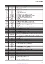
Main system clock input terminal (4 MHz)
Main system clock output terminal (4 MHz)
Ground terminal
Sub system clock input terminal Not used
Sub system clock output terminal Not used
Power supply terminal (+3.3V)
Ground terminal
Two-way data bus with the S-RAM
YAMAHA D2
Two-way data bus with the OSD controller and S-RAM
57
+3.3V
-
Power supply terminal (+3.3V)
58
GND
-
Ground terminal
59 to 63
SRAM IO11/YAMAHA
D3 to SRAM IO15/
YAMAHA D7
I/O
Two-way data bus with the OSD controller and S-RAM
64
YAMAHA PS0
O
Address signal output to the OSD controller
65, 66
SRAM A0/YAMAHA
PS1, SRAM A1/
YAMAHA PS2
O
Address signal output to the OSD controller and S-RAM
www. xiaoyu163. com
QQ 376315150
9
9
2
8
9
4
2
9
8
TEL 13942296513
9
9
2
8
9
4
2
9
8
0
5
1
5
1
3
6
7
3
Q
Q
TEL 13942296513 QQ 376315150 892498299
TEL 13942296513 QQ 376315150 892498299


