SRF-HM03V
5
2-4.
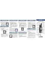
MICON BOARD, MAIN BOARD
1
six screws
(1.7)
3
two screws
(1.7)
5
claw
q;
two claws
qa
two claws
4
two screws
(B1.4)
6
cabinet assy front (R)
8
MICON board
qs
MAIN board
2
9
Remove the ten solders.
MAIN board
gray
white
blue
blue
yerrow
red
black
black
S1
Note: When installing the MAIN board, fit the knob and switch (S1).
7
connector
(CN301)
green
natural
2-3.
CABLE SETTING
Note:
When installing the POWER board, set the cables as shown figure.
POWER board
slit
slit
slit
slit
slit


