13
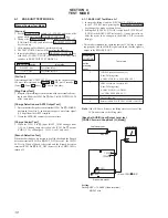
E) MMI Test
Command
Mode/Operation
Clears all EEPROM data.
Clears EEPROM ID data. If cleared successfully, sounds
the ACK beep.
Battery Save Mode
7-0-#
7-1-#
9-0-#
Command
Mode/Operation
Key matrix test
Does not function
Does not function
LED OFF
1) Press the SPEED key and turn off the BATT LOW
LED. (Basic)
Press the One-Touch key and turn off the LCD Back-
light LED. (CID/LCD)
2) Press the SPEED key and turn off the TALK LED
(Basic)
Press the One-Touch key and turn off the DIAL LED.
(CID/LCD)
3) Press the SPEED key and turn off the DIAL LED
(Basic)
Press the One-Touch key and turn on all LEDs and
return to step 1. (CID/LCD)
4) Press the SPEED key and turn on all LEDs and re-
turn to step 1. (Basic)
5-1-#
5-2-#
5-3-#
5-4-#
Note
: Key Matrix Test: 5-1-#
• If the keys are pressed continuously in the following desig nated
order correctly, a confirmation beep sounds.
If pressed incorrectly, an error beep sounds and the unit re
turns to the idling state.
TALK
n
OFF
n
FLASH
n
REDIAL
n
PGM
n
PAUSE
n
1
n
2
n
3
n
4
n
5
n
6
n
7
n
8
n
9
n
n
0
n
#
n
SPEED
F) Others
*
4-3-1. Ending the HANDSET Test Mode
1. Entering the command “0-0-#” from the keypad in any state of
the HANDSET TEST MODE ends the HANDSET MODE and
returns the normal mode.
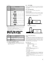
Jig antenna
(Utilize the antenna for handset)
Spectrum
analyzer
10 cm
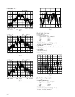
[Check the Transmission Wave]
Purpose
It is necessary to check spectrum wave of transmission wave which
is an important factor in order to confirm operational performance
of Spread Spectrum models. If this wave deviates from correct wave
form, normal data transmission cannot be made and, as a result of
that, possibility that occurrence of mute increases and communica-
tion distance becomes shorter will increase.
Measuring process
• Setting Spectrum analyzer:
Center frequency : 904.2 kHz (CH1)
RBW
: 30 kHz
VBW
: 30 kHz
Span
: 3 MHz (or 5MHz)
• Setting Test mode:
Continuous Transmit mode (CH1 High Power)
(Refer to “Test Mode” on page 10)
• Measurement:
Measure transmitting wave.
• Specifications:
Acceptable level [XdB] difference between the highest peak and
the lowest peak of odd side band (the first to seventh side band
from Center Frequency ; Transmission Frequency f
0
: CH1) is under
10 dB. (Refer Fig. 1 and Fig. 2)
If output wave form deteriorates, side band appears like Fig. 3
and Fig. 4.
4-4.
RF TESTING
This test is for checking the RF system without disassembling the
set in servicing. Perform measurement using the spectrum analyzer
and jig antenna.
4-4-1. RF Testing method
Please follow the below instruction to perform RF test.
[Setting Condition]
Connect a receiving antenna to RF INPUT of Spectrum analyzer
and set the unit 10 cm (4 inches) away from the receiving antenna.
Measuring tool: Spectrum analyzer (equivalent to HP8595E)
Jig: Receiving antenna (for Spectrum analyzer)
10 cm
Spectrum
analyzer
Содержание SPP-S9000 - Cordless Telephone
Страница 3: ...3 SECTION 1 GENERAL This section is extracted from instruction manual ...
Страница 4: ...4 ...
Страница 5: ...5 ...


