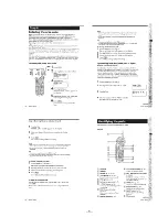


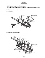


3-1. HANDSET
1. Test Mode
Entry— Press “PGM” key and enter “ TEST” on keypad.
Alternative entry— Write 99h into LSB of location 9 in EEPROM.
Exit— Press on “OFF” key.
LCD test— Press the “7” key.
Toggle TX power— Press the “0” key.
Increment RF channel— Press the “#” key.
2. Test Equipment Required and Connection
– 19 –
– 20 –
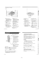
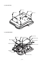
3-2. BASE UNIT
1. Test Mode
Entry— Simultaneously press the “HANDSET LOCATOR” key and toggle the “DIAL MODE” switch. When in test mode, the “IN USE”
and “CHARGE” LEDs will be light on.
Alternative entry— Write 99h into LSB of location 9 in EEPROM.
Exit— Remove the AC power adaptor.
Toggle TX power— DIAL MODE switch (S4001)
T (TONE) position : TX ON
P (PULSE) position : TX OFF
Increment RF channel— Press the “INTERCOM” key.
2. Test Equipment Required and Connection
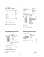
3. Verify Procedure
Item
Remark
18.4MHz Frequency Error
Connect the frequency counter to the test point J1, press “0” key to turn on the TX power. Then, check
the frequency ± 1 kHz. If the result is within ± 1 kHz, then no adjustment required. Otherwise, refer to
item 4. for Adjustment Procedure.
4. Adjustment Procedure
Item
Adjustment Element
Remark
18.4MHz Frequency Error
C4016
1. Remove C4017 from the BASE MAIN board.
2. Solder an 20PF chip capacitor C4016 (1-164-160-11) on the
BASE MAIN board (in parallel of C4014).
3. Connect the frequency counter to the test point J1. Adjust for 0 Hz ± 1 kHz.
SECTION 3
ELECTRICAL ADJUSTMENTS
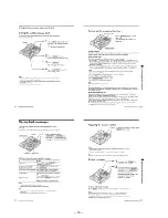
3. Verify Procedure
Item
Remark
18.4MHz Frequency Error
Connect the frequency counter to the test point J1, press “0” key to turn on the TX power. Then, check
the frequency ± 1 kHz. If the result is within ± 1 kHz, then no adjustment required. Otherwise, refer to
item 4. for Adjustment Procedure.
4. Adjustment Procedure
Item
Adjustment Element
Remark
18.4MHz Frequency Error
C1030
1. Remove C1031 from the HAND MAIN board.
2. Solder an 20PF chip capacitor C1030 (1-164-160-11) on the
HAND MAIN board (in parallel of C1029).
3. Connect the frequency counter to the test point J1. Adjust for 0 Hz ± 1 kHz.
*
J1
frequency
counter
J1003
J1004
BATTERY
3.6V
U1001
C1031
C1030
C1029
– HAND MAIN BOARD –
– RF UNIT (HS) –
J1
frequency
counter
– BASE MAIN BOARD
(SIDE B) –
– RF UNIT (BU) –
U4001
C4016
C4017
C4014
– BASE MAIN BOARD
(SIDE A) –
*
Содержание SPP-A973 - Cordless Telephone With Answering System
Страница 3: ... 3 SECTION 1 GENERAL This section is extracted from SPP A974 s instruction manual ...
Страница 4: ... 4 ...
Страница 5: ... 5 ...
Страница 6: ... 6 ...
Страница 7: ... 7 ...
Страница 8: ... 8 ...
Страница 9: ... 9 ...
Страница 10: ... 10 ...
Страница 11: ... 11 ...
Страница 12: ... 12 ...
Страница 13: ... 13 ...
Страница 14: ... 14 ...
Страница 18: ... 18 2 7 I TAD BOARD 3 I TAD board BASE KEY board 2 BTP 3x12 1 Removal the solders ...
Страница 27: ...SPP A973 A974 4 7 SCHEMATIC DIAGRAM I TAD SECTION Refer to page 45 for IC Block Diagrams 35 36 Page 27 Page 39 ...
Страница 31: ...SPP A973 A974 4 11 SCHEMATIC DIAGRAM HAND MAIN SECTION Refer to page 45 for IC Block Diagrams 43 44 ...


