— 2 —
TABLE OF CONTENTS
Notes on chip component replacement
• Never reuse a disconnected chip component.
• Notice that the minus side of a tantalum capacitor may be
damaged by heat.
Flexible Circuit Board Repairing
• Keep the temperature of soldering iron around 270˚C
during repairing.
• Do not touch the soldering iron on the same conductor of the
circuit board (within 3 times).
• Be careful not to apply force on the conductor when soldering
or unsoldering.
SECTION 1
GENERAL
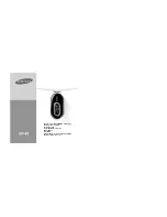
1
∑
VOL (volume) knob
2
BATT (battery) lamp
3
TUNING knob
4
FUNCTION selector
5
AVLS selector
6
MEGA BASS selector
7
)
REW button
8
(
PLAY button
9
0
FF button
0
p
STOP button
!¡
TAPE/FM MODE switch (AEP, E Model)
TAPE/FM SENS switch (US, CND, MX Model)
!™
2
jack
• Abbreviation
CND : Canadian model
MX
: Mexican model
1. GENERAL
·········································································· 2
2. SERVICE NOTE
2-1.
How to Install The Wire Assembly ····································· 3
2-2.
Water Proof Section ···························································· 3
3. DISASSEMBLY
3-1.
Holder Cassette Sub Assembly and Dial Scale ·················· 4
3-2.
Main Assembly ··································································· 5
3-3.
Main Board ········································································· 6
3-4.
Mechanism Deck ································································ 6
3-5.
Belt ····················································································· 7
3-6.
Magnetic head ···································································· 7
4. MECHANICAL ADJUSTMENT
·································· 8
5. ELECTRICAL ADJUSTMENT
···································· 8
6. DIAGRAMS
6-1.
Block Diagram ································································· 11
6-2.
Printed Wiring Board ························································ 13
6-3.
Schematic Diagram ·························································· 15
6-4.
IC Block Diagrams ··························································· 17
7. EXPLODED VIEWS
·················································
18
8. ELECTRICAL PARTS LIST
···································
23
1
0
9
8
7
2
3
4
5
6
!¡
!™