SLT-A58K/A58M/A58Y_L2
1-1
1. SERVICE NOTE
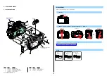
1-2. PRECAUTION ON REPLACING THE AM-1001 BOARD
Destination Data
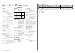
When you replace to the repairing board, the written destination data of repairing board also might be changed to original setting.
USB Serial No.
The set is shipped with a unique ID (USB Serial No.) written in it.
This ID has not been written in a new board for service, and therefore it must be entered after the board replacement.
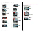
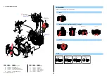
1-1. METHOD FOR REPLACING THE P.O.I.
Method of Removal
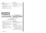
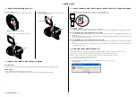
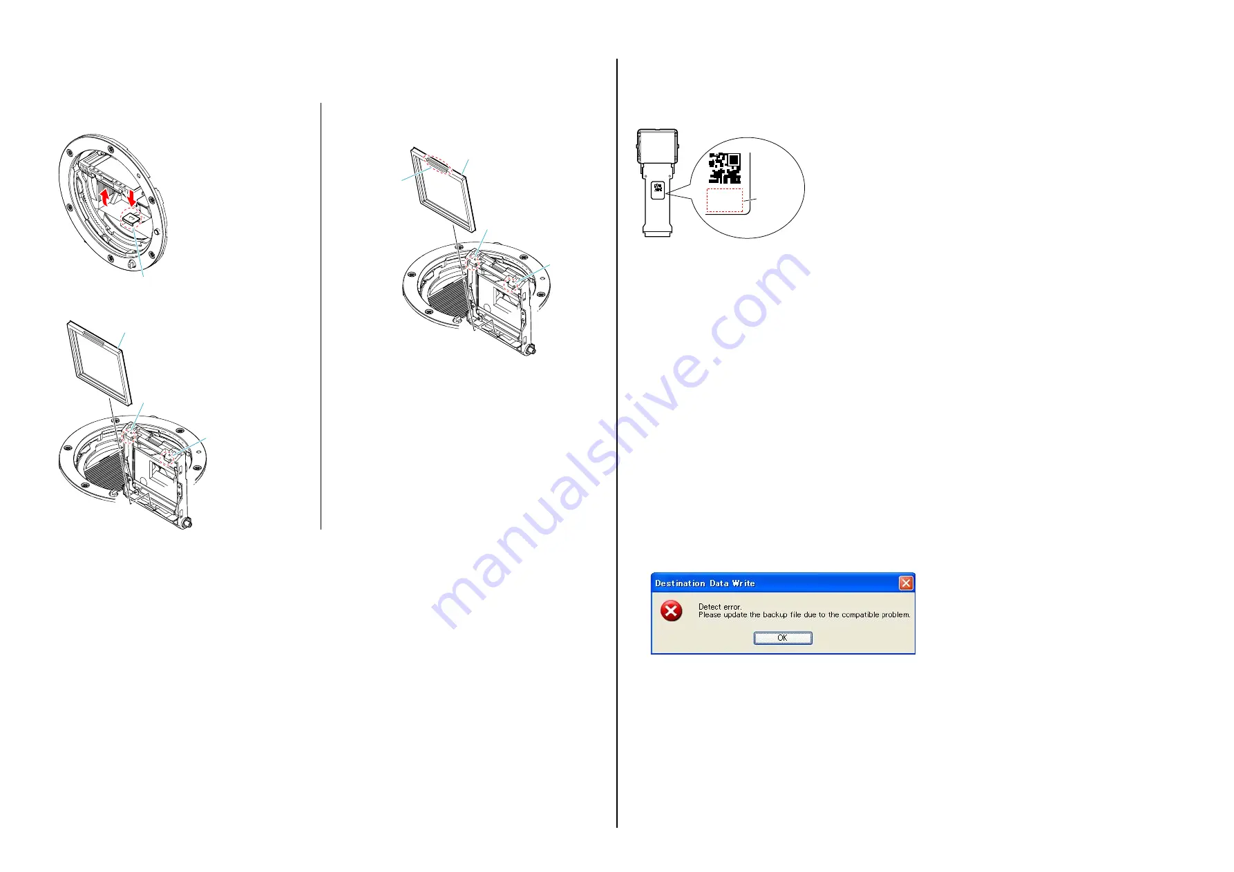
(1) Press the MB Mirror Frame Holder Lock SP to raise the P.O.I.
MB Mirror Frame Holder Lock SP
(2) Unjoint the two claws while pressing the P.O.I. backward.
Claw
Claw
P.O.I.
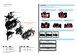
Method of Attachment
(1) When attaching the P.O.I., make the concave side of it face the
front and attach it downward.
Claw
Claw
P.O.I.
Concave side
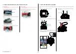
1-3. NOTES FOR REPLACING THE EVF DISPLAY DEVICE (LCD902) OR THE AM-1001 BOARD
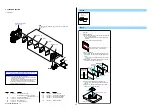
WB adjustment values of each EVF display device (LCD902) are stored on the AM board.
Therefore, when the LCD902 or the AM board has been replaced, write WB adjustment values.
Adjustment
value
1-A
1-A
When LCD902 is replaced:
1. Check and write down the adjustment values printed on the LCD902 label.
2. After the LCD902 has been replaced, execute “EVF WB Adj” on the ADJUST tab by using the Adjust manual to write the adjustment values.
When replacing AM board (in case adjustment values can be read):
1. In case the unrepaired unit starts and adjustment values can be read by using the Adjust manual, execute “ADJUSTMENT DATA BACKUP” on
the DATA tab.
2. After the AM board has been replaced with a AM board for repair, execute “ADJUSTMENT DATA BACKUP” on the DATA tab of the Adjust
manual to write the extracted data to the unit.
When replacing AM board (in case adjustment values cannot be read):
1. When adjustment values cannot be read from the unrepaired unit, disassemble the unit and write down the adjustment values printed on the LCD902
label.
2. After the AM board has been replaced with a AM board for repair, execute “EVF WB Adj.” on the ADJUST tab by using the Adjust manual to
write adjustment values to the unit.
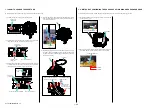
1-4. ADDITION OF DESTINATION DATA FILE
If the Destination Data file included in the Adjust manual is old, “DESTINATION DATA WRITE” cannot be executed in some cases.
In that case, download a new Destination Data file from the TISS homepage according to the following procedure.
Note 1:
To perform Destination Data Write for this model, the Adjust manual of the DSC-WX50 series must have been installed.
Install the Adjust manual of the DSC-WX50 series in advance.
Note 2:
The actual image may differ from the image shown above.
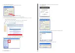
1) If the Destination Data file in the Adjust manual in use is old, the window shown in Fig. 1 is displayed.
Click the [OK] button.
Fig.
1


