SDM-S51(E)
2-2
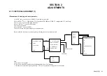
2-2. FUNCTIONAL ALIGNMENT (2)
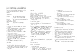
This paper documents the functional alignment (Used
Color meter) procedure of Sony LCD monitor
SDM-S51.
• Equipm ent
Computer: PC workstation with Windows 95
Installed PS/2 mouse is required
Software:
KSi Engineering alignment software tool
Color meter:
Option
Signal generator: Option
Cable: Special RS232 interface cable
• Setup
1. Copy ECS software <ALIGN.EXE> into a new PC
directory.
2. Prepare timing & pattern data for signal generator
according to Sony’s timing specifications.
3. Prepare timing files for <ALIGN.EXE>.
4. Connect monitor interface cable between flat panel
monitor and PC com port.
5. Connect monitor video cable to signal generator.
6. Put Topcon 50cm from the monitor; Point it
perpendicularly at the center of the display; Achieve
the best focus through the eyepiece.
7. Enclose the monitor and Topcon in a light-shield
chamber.
8. Set up [SERVICE MODE] of the monitor.
• Download
In order to enhance productivity, a software utility is
provided to download default data to LCD monitor. The
default data includes color balance data and geometry
timing data.
• Operation
1. Execute software <ALIGN.EXE>.
2. Click on ‘Setup’ menu.
3. Select ‘Monitor’ type as ‘Sony SDM-S81 ’.
4. Select ‘COM PORT’ according to hardware connection.
5. Click <OK> to save the new setup configuration.
6. Quit this application and Re-enter to make the new
settings effective.
• On Scr een Adj ustment
1. Click on the ‘Monitor’ icon; an virtual monitor panel
would show up.
2. On entry, the software tries to establish a communication
link
with the monitor.
The monitor internal DACs
are read and shown on screen sliders. A ‘CONNECT’
icon would show up on the lower left corner of the
dialog screen.
3. An error message would pop up should communication
fail. A ‘BREAK’ icon would show up on the dialog
screen. If this happens, check the hardware setup,
communication cable, and the connection.
• Warm up time
Allow 30 minutes warm up time before doing any adjust-
ment.
• Color Adjustm ent
1. 9300K color adjustment
--Center adjustment--
a. Click ‘Color Temperature’ as ‘9300’.
b. Apply 40% IRE white video field, primary mode.
c. Make sure ‘backlight’ register data is 0 (100%).
d. Click ‘Refresh’.
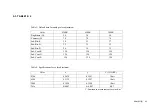
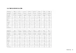
Refer to table 1 for default data for color
adjustment.
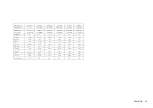
e. Adjust ‘sub_brt_B’ to achieve color temperature.
Refer to table 2 for specification.
f. Click ‘Save this color’ for a 9300K color save.
2. 5000K color adjustment
a. Click ‘Color Temperature’ as ‘5000’.
b. Repeat alignment procedure as 9300 steps b-f.
3. 6500K
color adjustment
a. Click ‘Color Temperature’ as ‘6500’.
b. Repeat alignment procedure as 9300 steps b-f.
• Geometry Adjus tment
Connect the personal computer which has alignment
data.
2. Click ‘Refresh’ (inside Geometry Register Box).
3. Adjust ‘Pitch’ for optimum screen performance.
4. Adjust ‘Phase’ for optimum screen performance.
5. Adjust ‘H position’ to make the screen center
horizontally.
6. Adjust ‘V position’ to make the screen center vertically.
7. Repeat steps 3-6 for best picture performance.
8. Click ‘Save Geometry’ to perform a user timing mode
save.
9. Repeat step 1-7 for each of the user present timings.
1.
Содержание SDM-S51
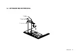
Страница 8: ...SDM S51 E 1 2 1 2 KEYBOARD MOUNT REMOVAL 2 Four screws PVTP 3x10 1 Screw PWH 3x4 3 Keyboard mount ...
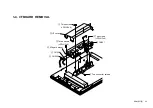
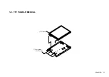
Страница 11: ...SDM S51 E 1 5 1 5 TFT PANEL REMOVAL 1 Four screws PVTP 4x12 2 TFT panel ...
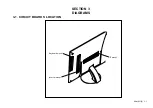
Страница 18: ...SDM S51 E 3 1 3 1 CIRCUIT BOARDS LOCATION SECTION 3 DIAGRAMS Inverter mount Keyboard mount I F mount ...
Страница 24: ...SDM S51 E 69 9 978 721 01 English 2001LL08 Data Made in Japan 2001 12 ...

