


SCD-XE800
12
SERVICE MODE (2)
1. Service Mode (2) General Description
This mode let you make diagnosis and adjustment easily by us-
ing the remote commander and the TV screen for Composite in-
put. The instructions, diagnostic results, etc. are given on the TV
screen.
Be sure to execute the IOP measurement when a base unit is re-
placed.
Preparations:
Prepare a TV monitor that has a Composite input.
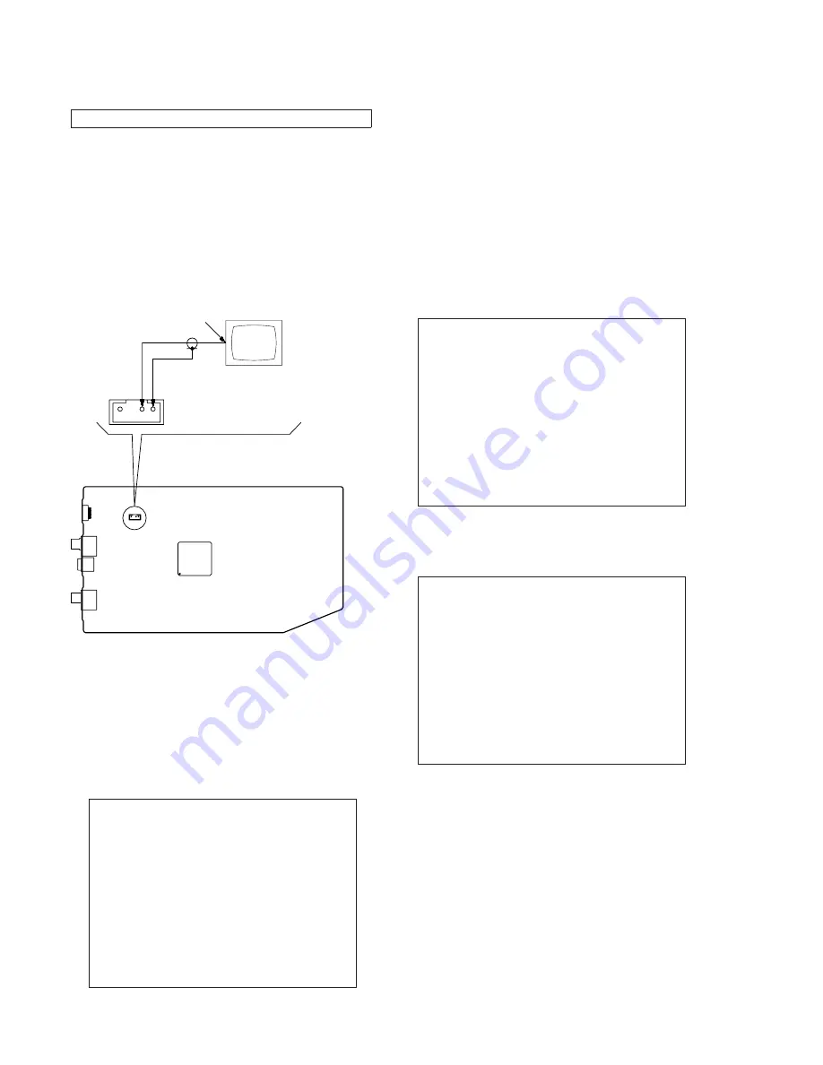
Connection Procedures:
Connect the TV monitor to CN1801 on the MAIN board as shown
in the diagram.
– MAIN Board (Component Side) –
3 4
IC1101
VBOUT
GND
TV monitor
CN1801
Composite input
2. Entering Service Mode (2)
Procedure:
1. Press the [
?/1
] button to turn the power on.
2. Press two buttons of [
x
] and [
Z
] on the set simultaneously for
3 seconds
3. The message “SERVICE IN” appears on the fl uorescent indi-
cator tube and top menu of the Remocon Diagnosis Menu ap-
pears on the on-screen display on the TV screen for Composite
input as follows. The model name, IF-con version and Syscon
version are displayed at the bottom of the on-screen display.
Remocon Diagnosis Menu
0. External Chip Check
1. Servo Parameter Check
2. Drive Manual Operation
3. Emergency History
4. Version Information
Model Name :xxx-xxxxx
IF-con:Ver.xx.xx(xxxx)
Syscon:Ver.x.xxx
4. To execute each function, press its number by using numeric
button on the remote commander.
5. To release from this mode, disconnect the power cord.
Note:
Don't press the [
?/1
] button when to release from this mode. Nec-
essarily disconnect the power cord. The set doesn't operate when
turning off power with [
?/1
] button of the set.
3. Executing IOP Measurement
In order to execute IOP measurement, the following standard pro-
cedures must be followed.
Procedure:
1. From the top menu of Remocon Diagnosis Menu, select “2
Drive Manual Operation” by pressing the [2] button on the
remote commander. The following screen appears on the on-
screen display
Drive Manual Operation
1. Servo Control
2. Track/Layer Jump
3. Manual Adjustment
4. Mecha test mode
5. MIRR time Adjust
0. Return to Top Menu
2. Select “3. Manual Adjustment” by pressing the [3] button on
the remote commander. The following screen appears on the
on-screen display.
Manual Adjust
1. Track Balance Adjust:
2. Track Gain Adjust:
3. Focus Balance Adjust:
4. Focus Gain Adjust:
5. Eq Boost Adjust:
6. Iop:
7. TRV. Level:
8. S curve(FE) Level:
9. RFL(PI) Level:
0. MIRR Time:
[
V
][
v
] Change Value
[RETURN]Return to previous menu
3. Select “6. Iop:” by pressing [6] button on the remote com-
mander.
4. Wait until a hexadecimal number appear in the on-screen dis-
play as below.
Note: SERVICE MODE (2) is a service mode of Super Audio CD.
Содержание SCD-XE800
Страница 4: ... Bottom view ...
Страница 6: ...SCD XE800 2 3 POWER BOARD 2 4 PANEL LOADING 6 ...
Страница 7: ...SCD XE800 2 5 FRONT PANEL BLOCK 2 6 CD MECHANISM DECK BLOCK CDM66F1 DVBU101 Note 1 ß 7 ...
Страница 8: ......
Страница 9: ...SCD XE800 2 9 BASE UNIT 2 10 OPTICAL PICK UP BLOCK KHM 313CAB 9 ...
Страница 14: ......
Страница 15: ......
Страница 17: ......
Страница 18: ......
Страница 19: ......
Страница 20: ......
Страница 21: ......
Страница 22: ......
Страница 23: ......
Страница 24: ......
Страница 25: ......
Страница 26: ......
Страница 27: ......
Страница 37: ...SCD XE800 5 2 CHASSIS SECTION 37 ...
Страница 38: ...SCD XE800 5 3 MECHANISM DECK SECTION CDM66F1 DVBU101 38 ...
Страница 39: ...SCD XE800 5 4 BASE UNIT SECTION 39 ...


