Sony SAL-1680Z Скачать руководство пользователя страница 77

4-31

SAL1680Z (Vario-Sonnar DT 3.5-4.5/16-80 ZA) (Vario-Sonnar T

*

 DT 16-80mm F3.5-4.5 ZA)

3)

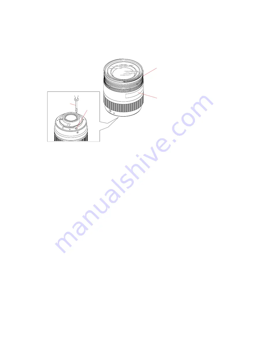
Hold the lower part of MF operation ring by hand and rotate it clockwise to tighten it to the lens unit.

4)

When rotating the MF operation ring, confirm that the focus scale plate moves following the MF operation ring.

When rotating the coupler at the lens mount side with a screwdriver, confirm that the MF operation ring does not rotate.

If these two items are not met the specifications simultaneously, adjust the extent of tightening of MF operation ring to the lens unit

in step 3.

Fig.4-8-3

MF Operation Ring

Focus Scale Plate

Screwdriver

Coupler

Содержание SAL-1680Z

Страница 1: ... How to use Acrobat Reader Ver 1 5 2008 09 LENS FOR DSLR CAMERA 2008I0800 1 2008 09 Published by Kohda TEC 9 852 120 14 US Model Canadian Model AEP Model Chinese Model SAL1680Z Vario Sonnar DT 3 5 4 5 16 80 ZA Vario Sonnar T DT 16 80mm F3 5 4 5 ZA About the Lens Test Projector and Finished Inspection JIG About the Front Decoration Plate About the MTF measurement Revised 3 Replace the previously is...

Страница 2: ... on Digital Single Lens Reflex Cameras equipped with an APS C sized image sensor Lens groups elements 10 14 Angle of view 2 83 20 2 The value of angle of view is based on Digital Single Lens Reflex Cameras equipped with an APS C sized image sensor Minimum focus m feet 3 0 35 1 2 3 Minimum focus is the shortest distance from the image sensor to the subject Maximum magnification 0 24 Minimum f stop ...

Страница 3: ...s 4 1 4 2 Aperture Diameter Check adjustment 4 13 4 3 Projective Resolving Power Check Adjustment 4 18 4 4 Flange Back f F Check Adjustment 4 22 4 5 Focus Shift by Zooming Check Adjustment 4 25 4 6 Focus Scale Plate Position Adjustment 4 27 4 7 Focus shift Check Adjustment Aperture Amount of Spherical Aberration 4 29 4 8 Toruqe Adjustment of MF Operation Ring 4 30 4 9 Lens ROM Check 4 32 4 10 Zoom...

Страница 4: ...use chemicals to clean heavy dirt don t use paint thinner ketone nor alcohol Insert the specific screws vertically to the part when installing a exterior part Be careful not to tighten screws too much 1 3 Unleaded Solder This unit uses unleaded solder Boards requiring use of unleaded solder are printed with the lead free mark LF indicating the solder contains no lead Caution Some printed circuit b...

Страница 5: ...uch the soldering iron on the same conductor of the circuit board within 3 times Be careful not to apply force on the conductor when soldering or unsoldering SAFETY RELATED COMPONENT WARNING COMPONENTS IDENTIFIED BY MARK 0 OR DOTTED LINEWITH MARK 0 ON THE SCHEMATIC DIAGRAMS AND IN THE PARTS LIST ARE CRITICAL TO SAFE OPERATION REPLACE THESE COMPONENTS WITH SONY PARTS WHOSE PART NUMBERS APPEAR AS SH...

Страница 6: ...block Replace the lens mount block Perform the aperture diameter adjustment See page 4 16 Perform the aperture diameter check See page 4 13 NG Check the aperture operation of rear barrel assy OK OK OK Function NG F No NG Aperture trouble Replace the rear barrel assy NG NG NG END OK Perform the aperture diameter check See page 4 13 Ver 1 3 2008 05 The changed portions from Ver 1 2 are shown in blue...

Страница 7: ...or replace the zoom brush Check board pattern of the zoom flex pattern Clean the board pattern of zoom flex pattern Zoom trouble Replace the main flexible unit Perform the zoom brush position check adjustment See page 4 34 NG NG NG NG END OK Disassembly and check the zoom relation parts Replace the defective part or apply the grease Check the operation again Ver 1 3 2008 05 The changed portions fr...

Страница 8: ...ear shaft of the gear C D block Check the focus operation ring and focus lens holder NG NG NG NG NG END OK Check the position and deformation at the tip of the focus brush Check the position or replace the focus brush Check board pattern of the focus flex pattern Clean the board pattern Replace the main flexible unit Perform the focus brush position check adjustment and pattern check See page 4 42...

Страница 9: ...ad to the gilded flexible board UNIVERSAL WRENCH In case of the following notches or holes are located in the lens block etc during disassembling assembling the lens Use the universal wrench How to Use Attach the chip A or chip B to the universal wrench For the notches chip A For the holes chip B Match the universal wrench to the holes or notches of the lens block etc Notches Holes Universal wrenc...

Страница 10: ...9 3 4 Adjustment Washer 4 Light Shield Plate A HELP01 See page 2 3 About the front decoration plate Be sure avoiding replacement of front decoration plate as far as possible If replacement of it should be need you convey the message to your user that changing of the Carl Zeiss Serial No is needed and then you may obtain user s agreement and it replace Note Remove the 3rd Lens Block After replacing...

Страница 11: ...TER COVER BLOCK EXPLODED VIEW 9 Outer Cover Block HELP09 8 Rotation Cover Pin HELP08 7 Zoom Barrel HELP07 6 Zoom Hold Ring HELP06 1 Zoom Rubber Ring 3 Brush Cover B HELP04 2 Brush Cover HELP03 4 Brush Cover C HELP04 Flex Setting Tape B HELP02 5 Zoom Brush HELP05 See page 2 4 ZOOM BRUSH POSITION ADJUSTMENT Polyester Tape ...

Страница 12: ...LP11 HELP12 See page 2 5 HELP14 9 Coupler Adjustment Washer FLANGE BACK ADJUSTMENT 7 Gear C D Block 8 Coupler Bush 6 AF Coupler Stopper Screw 2 Ground Spring 1 Main Flexible Unit HELP10 3 Rear Light Shield Barrel 4 Lens Mount Block Main Spring Presetting Holder 5 Back Adjustment Washer FLANGE BACK ADJUSTMENT Presetting Ring Block ...

Страница 13: ...ale Plate Focus Stopper HELP19 6 Outer Barrel Assy HELP21 Main Flexible Unit HELP23 HELP20 4 MF Operation Ring HELP17 HELP18 HELP22 HELP15 HELP23 FOCUS SCALE PLATE POSITION ADJUSTMENT FOCUS SHIFT ADJUSTMENT MF OPERATION RING TORQUE ADJUSTMENT FOCUS BRUSH POSITION ADJUSTMENT Note When the MF operation ring is disassembled remove the adhesive bond below the MF operation ring with tweezers 3 location...

Страница 14: ... 16 80mm F3 5 4 5 ZA 2 1 5 REAR BARREL ASSY ZOOM CAM RING AND FOCUS COUPLING BARREL ASSY EXPLODED VIEW 1 Rear Barrel Assy HELP24 4 Outer Tube HELP27 5 Zoom Cam Ring HELP28 HELP26 2 Focus Coupling Barrel Assy HELP25 3 4th Operation Plate APERTURE DIAMETER ADJUSTMENT ...

Страница 15: ...igning the top of Z of Carl Zeiss shown in the figure with the hood index Note When affixing be careful not to damage the decorated side of front decoration plate HELP02 Affix the flex setting tape B evenly between the brush cover B and the brush cover C 5 5 Released Paper Hood Index Reference Position Hood Index HELP Zoom Barrel Zoom Barrel Flex Setting Tape B Flex Setting Tape B Brush Cover B Br...

Страница 16: ...the lower end of brush cover along the edge of zoom barrel 2 Affix the polyester tape black 10mm cut as instructed to the location shown in figure Note Affix the polyester tape black 10mm for the brush cover not to float Zoom Barrel Wind brush cover along this edge Brush Cover Brush Cover B Brush Cover C Polyester Tape Black 10mm 8x18mm Polyester Tape Black 10mm 8x18mm ...

Страница 17: ...ndary in concave and convex sides as a reference 2 Likewise peel the released paper from the brush cover C and affix it to the concave side of zoom barrel as shown in the figure referring the boundary in concave and convex sides as a reference Zoom Barrel Brush Cover B Reference to affixing Boundary in convex and concave Released Paper Zoom Barrel Brush Cover C Reference to affixing Boundary in co...

Страница 18: ...serting the projection of zoom barrel in the square hole at the center of brush install the zoom brush and move it in the arrow direction 2 Affix the polyester tape cut as instructed to the location shown in the figure Zoom Barrel Projection Square hole Zoom Brush Zoom Brush Polyester Tape 4x40mm ...

Страница 19: ... tape cut as instructed to the brush cover D as shown in the figure 4 Install the brush cover D at the position shown in the figure and fix it with the polyester tape Zoom Brush Zoom Brush Details of affixing position Almost same length Brush Cover D Brush Cover D Polyester Tape 4x20mm Polyester Tape 4x20mm ...

Страница 20: ... G A G 115 G 117 1 2 Mix grease at the following rates before using the grease and mix grease enough 2 Install the zoom hold ring placing its mount index at the position shown in the figure Then tighten three screws to fix zoom hold ring When tightening one of three screws remove the part of Lno Decoration plate Lno Decoration Plate Screw Screw Mount Index Screw Zoom Hold Ring Apply the grease G A...

Страница 21: ...enough Note Be careful not to apply the grease to the main flexible unit 2 Apply the anti diffusion agent A 20 to the indicated portion of zoom barrel 3 Apply the grease G B to the indicated portion of zoom barrel 4 Inserting the zoom coupling pin in the groove install the zoom barrel to the outer barrel assembly Apply the grease G B All circumference After apply the grease G B apply the grease G ...

Страница 22: ...ale window of outer cover block 2 Place the focus scale window of outer cover block to the index side insert three projections at inner side to the rib less portion of outer barrel assembly aligning them and rotate it in the arrow direction until it clicks 3 Confirm that no scar is found on the focus scale window and no grease is attached Apply the adhesive bond B 10 Outer Cover Block Outer Barrel...

Страница 23: ...ive bond B 40 J 6082 614 A Install the rear light shield barrel to the lens mount block apply the adhesive bond B 40 to the screwed portions of three screws shown in the figure and tighten the screws in the order of 1 to 3 Apply the adhesive bond B 40 Lens Mount Block Rear Light Shield Barrel 1 2 3 ...

Страница 24: ...n the arrow direction to close the aperture 3 Install the back adjustment washer 4 Linking the lever of preset ring to the groove of aperture operate plate of rear barrel assy install the lens mount block 5 Turning counterclockwise the lens mount block tighten diagonally four screws shown in the figure Screws Screws Lens Mount Block Lever of presetting ring Back Adjustment Washer Focus Operation R...

Страница 25: ... adhesive bond LOCTITE 460 to the tip of stopper screw and tighten it to the lens mount block HELP13 Oil O 20 J 6082 610 A 1 Apply a little amount of oil O 20 to the indicated portion of main spring 2 Hook the main spring to the lens mount block and presetting ring block as shown in the figure Lens Mount Block Apply the adhesive bond LOCTITE 460 Apply small amount of the oil O 20 On contacting are...

Страница 26: ...side 2 Peel off the polyester tape fixing the main flexible unit shown in the figure and lift up a little the main flexible unit with tweezers 3 Install the focus brush with two screws Note Install the focus brush in the direction shown in the detailed figure Coupler Adjustment Washer Apply the grease G 15 Gear Apply the grease G 15 Gear Apply the grease G 15 Top of shaft Coupler Bush AF Coupler G...

Страница 27: ...in and tighten the zoom coupling pin HELP17 1 Align the projection of focus ring B of MF operation ring block with the pinch lever 2 Aligning three projections of focus ring B with three cut portions of outer tube install the focus ring B Then holding its lower part by hand turn clockwise the MF operation ring block and install it Guide groove Index with red color Guide bush Index with red color G...

Страница 28: ...er B Wipe seeping out bond off and install the pinch lever B to the MF operation ring by the pinch lever shaft One location 6 Affix the friction sheet A to the inner side of focus ring B 7 Apply the anti diffusion agent A 20 grease G 55 and following grease G A to the indicated portion of torque ring Grease G A G 115 G 117 1 2 Mix grease at the following rates before using the grease and mix greas...

Страница 29: ...the gear side as shown in the figure and install it in the groove of focus ring 4 Aligning the end of gear of focus ring with the hole of outer barrel as shown in figure assemble the focus ring into the outer barrel assembly 5 Turn a little clockwise the focus ring so that the screw holes of focus stopper can be seen in the two holes of outer barrel assembly 6 Tighten two screws Long Short Focus R...

Страница 30: ...nstall the focus scale plate Affix the polyester tape black 10mm cut as instructed to the location shown in figure Note Install the focus scale plate in the direction marked with characters in the figure Fix the focus scale plate with the polyester tape black 10mm not to loose 20 2mm Focus Ring Cut portion Reference position to winding Groove Focus Scale Plate Character direction of focus scale pl...

Страница 31: ... outer tube block 3 Inserting the installation part of coupler in the cut portion of outer tube block assemble the outer barrel assembly At this moment insert the lever of focus operation ring in the lever groove of focus lens holder 4 While pushing and rotating clockwise the outer barrel assembly tighten diagonally four screws shown in the figure AF coupler installing position Outer Barrel Servic...

Страница 32: ...before using the grease and mix grease enough 2 Apply the grease G 15 to the indicated portions of A B block 3 Inserting the lever of focus operation ring in the cut portion of inner side of outer barrel assembly install the focus operation ring 4 Engage the gear A B block with gear of focus operation ring and tighten two screws to fix the gear A B block Screw Gear A B Block Focus Operation Ring O...

Страница 33: ...r tape cut as instructed to the location shown in figure Fold back this portion and then affix it to the inner side of outer barrel 8 6 7 5 4 3 1 2 Flex Setting Tape A Flex Setting Tape B Flex Setting Tape C Friction Sheet C Friction Sheet C Flex Setting Tape D Flex Setting Tape E Main Flexible Unit Outer Barrel Polyester Tape 4x20mm Polyester Tape 4x20mm Apply the anti diffusion agent A 20 All ci...

Страница 34: ... so that the 4th operation plate comes in the middle groove position at the side of outer tube of two small legs of outer tube At this moment confirm that the narrow width lever of focus coupling barrel assy positions at the location shown in the figure 2 Aligning the screw hole with the linear guide groove at the side adjust the rear barrel assembly to reference position Leg Leg 4th Operation Pla...

Страница 35: ... d 3 197 211 01 3rd Lens Block Guide Roller 4 81 4 61 3 197 212 01 3rd Lens Block Guide Roller 4 81 4 62 3 197 213 01 3rd Lens Block Guide Roller 4 81 4 63 3 197 216 01 3rd Lens Block Guide Roller 4 82 4 61 3 197 217 01 3rd Lens Block Guide Roller 4 82 4 62 3 197 218 01 3rd Lens Block Guide Roller 4 82 4 63 3 197 219 01 3rd Lens Block Guide Roller 4 83 4 61 3 197 220 01 3rd Lens Block Guide Roller...

Страница 36: ...ns at the inner side of coupling barrel into three grooves of 2nd lens holder 3 Rotate fully the coupling barrel of focus coupling barrel assy assembled in step 3 in the arrow direction and turn it back a little so that the left end of projection aligns with the right end of projection at the screw hole of focus lens holder as shown in the figure 4 Rotate fully the zoom cam ring of outer tube in t...

Страница 37: ...3 locations Par Number Part Name Dimension mm Diameter of D 3 197 202 01 2nd Lens Block Guide Roller 4 31 3 197 203 01 2nd Lens Block Guide Roller 4 32 3 197 204 01 2nd Lens Block Guide Roller 4 33 7 Install the 2nd lens block guide spring and 2nd lens block guide bush and tighten them with three screws 3 locations Focus coupling barrel assy Narrow Lever Projection Projection Groove of outer tube ...

Страница 38: ... After assembling confirm that the installation part of 4th operation plate locates at the side where the distance between legs is wider as shown in the figure 2 Tighten the 4th operation plate with the screw of which screwed portion is applied with the adhesive bond B 40 Zoom Cam Ring Outer Tube 4th operation plate mounting position 4th Operation Plate Narrow Wide Reference Line Wide Narrow 4th o...

Страница 39: ...ease and mix grease enough HELP28 Grease G 116 J 6082 628 A Grease G 117 J 6082 660 A Apply the following grease G B to the indicated portion of zoom cam ring Grease G B G 116 G 117 1 2 Mix grease at the following rates before using the grease and mix grease enough Apply the grease G B Guide roller groove six locations Apply the grease G B Straight guide groove three locations Apply the grease G B...

Страница 40: ...G 10 3 197 144 01 LIGHT SHIELD PLATE B NOTE XX and X mean standardized parts so they may have some difference from the original one Items marked are not stocked since they are seldom required for routine service Some delay should be anticipated when ordering these items The mechanical parts with no reference number in the exploded views are not supplied Note 1 Be sure avoiding replacement of front...

Страница 41: ... POLYESTER TAPE Note 1 60 9 913 210 03 POLYESTER TAPE BLACK 10mm Note 2 61 3 197 145 01 BRUSH COVER 62 3 197 258 01 SCREW 1 7X4 0 63 A 1253 997 A ZOOM HOLD RING 65 3 197 279 01 MODEL NUMBER NAME 66 3 197 282 01 ZOOM RUBBER RING Ref No Part No Description See page 3 3 51 52 ns 54 60 61 63 65 62 66 62 62 59 60 59 59 57 56 55 58 Note 2 8 x 18mm Note 2 8 x 18mm Note 1 4 x 40mm Note 1 4 x 20mm Note 1 3...

Страница 42: ...T WASHER Note 1 105 3 197 150 01 PRESETTING HOLDER 106 3 197 186 01 MAIN SPRING 107 A 1254 103 A PRESETTING RING BLOCK 108 3 197 198 01 STOPPER SCREW 109 A 1253 996 A LENS MOUNT BLOCK 110 3 197 267 01 SCREW M2 0X5 0 111 3 197 140 01 REAR LIGHT SHIELD BARREL 112 3 197 188 01 SCREW M1 4X2 2 113 3 197 189 01 GROUND SPRING 114 3 197 257 01 TAPPING SCREW M1 7X4 0 115 3 214 828 01 COUPLER BUSH Ref No Pa...

Страница 43: ...97 193 01 FOCUS STOPPER 163 3 197 278 01 FOCUS SCALE PLATE 164 9 913 210 03 POLYESTER TAPE BLACK 10mm Note 1 165 3 197 259 01 SCREW M1 7X5 0 166 A 1254 104 A GEAR A B BLOCK 167 3 197 139 01 FOCUS OPERATION RING 168 3 197 072 01 OUTER BARREL 169 3 197 190 01 SCREW M1 4X2 5 170 3 197 153 01 FOCUS BRUSH 171 9 913 210 00 POLYESTER TAPE Note 2 172 A 1254 106 A MAIN FLEXIBLE UNIT 173 3 197 256 01 SCREW ...

Страница 44: ...197 146 01 4TH OPERATION PLATE 205 3 197 135 01 OUTER TUBE 206 Selection parts 3RD LENS BLOCK GUIDE ROLLER Note 1 207 3 197 210 01 3RD LENS BLOCK GUIDE PIN 208 Selection parts 2ND LENS BLOCK GUIDE ROLLER Note 1 209 3 197 208 01 2ND LENS BLOCK GUIDE SPRING 210 3 197 201 01 2ND LENS BLOCK GUIDE BUSH 211 3 197 260 01 SCREW M1 7X7 0 212 A 1253 988 A REAR BARREL ASSY Ref No Part No Description 3 1 5 RE...

Страница 45: ...0mm 2 683 652 01 BACK ADJUSTMENT WASHER E t 0 50mm Ref No 206 Select the type of part according to the operation load of the associated parts Part No Description 3 197 211 01 3RD LENS BLOCK GUIDE ROLLER D 4 81mm d 4 61mm 3 197 212 01 3RD LENS BLOCK GUIDE ROLLER D 4 81mm d 4 62mm 3 197 213 01 3RD LENS BLOCK GUIDE ROLLER D 4 81mm d 4 63mm 3 197 216 01 3RD LENS BLOCK GUIDE ROLLER D 4 82mm d 4 61mm 3 ...

Страница 46: ...TION JAPANESE ENGLISH FRENCH SPANISH SIMPLIFIED CHINESE 2 685 147 11 MANUAL INSTRUCTION GERMAN DUTCH SWEDISH ITALIAN AEP 2 685 147 22 MANUAL INSTRUCTION PORTUGUESE RUSSIAN TRADITIONAL CHINESE KOREAN ARABIC AEP Lens Hood SH0005 2 687 328 01 Front Lens Cap X 2176 982 1 Rear Lens Cap 2 683 615 01 Lens Case 2 694 833 01 Ver 1 3 2008 05 The changed portions from Ver 1 2 are shown in blue ...

Страница 47: ...le InstaCal exe Color Calculator 2 Note Color Calculator 2 is downloadable from the ESI homepage Fig 4 1 1 Personal computer Note 1 AE master lens J 6082 597 A Flange back gauge 43 50mm J 6082 608 A Maximum Aperture jig J 6082 640 A Aberration measuring cap 62mm SAL1680Z J 6082 658 A Flange back tester J 6082 606 A A mount attachment J 6082 607 A Lens test projector J 6082 605 A Note 3 1000 mm Col...

Страница 48: ...rd disk free area 15 M Byte or more recommended USB terminal Standard equipment Graphics 32 000 colors or more recommended VGA monitor Note 2 Attach the chart to the 1000 mm collimator as shown in Fig 4 1 2 Fig 4 1 2 Note 3 Connect the variable transformer Output voltage AC 100 V to the lens test projector Note 4 Finished Inspection JIG is AC 100 V only Align the marks 1000 mm collimator Chart ...

Страница 49: ...Equipment used Personal Computer Lens Adjustment Program ActuatorChecker Ver x x x x zip PC Card Setup File InstaCal zip Note 1 Lap top PC with PC card slot on which Windows XP runs Note 2 Obtain the PC card setup file InstaCal zip from the ESI homepage Note 3 Obtain the lens adjustment program ActuatorChecker Ver x x x x zip from the ESI homepage 1 Download of PC card setup file InstaCal exe 1 Cr...

Страница 50: ... MCC for the extract destination folder Fig 4 1 5 6 The window returns to the menu to specify the extract destination folder Click Unzip Fig 4 1 6 7 When the window below appears click OK Fig 4 1 7 8 Return to the menu to specify the extract destination folder Then click Close to close the window ...

Страница 51: ...m F3 5 4 5 ZA 2 Setup of PC Card 1 Double click InstaCal msi in C MCC folder to begin the installation Fig 4 1 8 2 The menu to begin the installation appears Click Next Fig 4 1 9 3 Specify the install destination folder As the default is used for it click Next Fig 4 1 10 ...

Страница 52: ...l Fig 4 1 11 5 The installation is completed Click Finish Note To refer to the readme file check the Show the readme file and click Finish Fig 4 1 12 6 To make the configuration installed effective the window to prompt the restart appears Click Yes to restart the PC Note If a device is connected without restarting the program may not work properly Fig 4 1 13 ...

Страница 53: ...restarting the PC insert the PC CARD DIO48 in the PC card slot 8 The software installation window appears Click Install the software automatically Recommended Fig 4 1 14 9 The software is detected and installed When the window below appears click Finish to terminate the installation Fig 4 1 15 ...

Страница 54: ...Note Depending on the Windows setting the window below may differ Fig 4 1 16 2 When PC CARD DIO48 is detected the window below appears Confirm that the PC CARD DIO48 is checked Note Depending on the slot inserted the slot No differs Fig 4 1 17 3 Confirm that PC CARD DIO48 is recognized as Board 0 Note If not recognized as Board 0 the program does not work properly Fig 4 1 18 4 Click File Exit to t...

Страница 55: ...ctuatorChecker exe 1 Download the file ActuatorChecker VerX X X X zip from Service Fixture and Software of ESI homepage save and extract it 2 Start up ActuatorChecker exe from an arbitrary folder 3 If PC CARD DIO48 is properly installed the window below appears Note The version of ActuatorCheker might be updated Fig 4 1 19 ...

Страница 56: ...fore this procedure is executed Equipment Personal Computer Finished Inspection JIG AC100 V only Lens Adjustment Program ActuatorChecker exe 1 Connect equipment and checking lens as shown Fig 4 1 20 Fig 4 1 20 2 Turn on the finished inspection JIG 3 Turn on the personal computer 4 Start up ActuatorChecker exe from an arbitrary folder conform that start up program normally Note Turn off the finishe...

Страница 57: ...Checker 1 Start up ActuatorChecker exe Fig 4 1 21 2 Depending on the initial startup or setting made at the previous startup the window differs When the English window appears click the Set up button Note When any button is clicked the Serial window appears The window to enter the lens serial number appears Fig 4 1 22 ...

Страница 58: ...click OK Fig 4 1 23 4 1 5 About Inspection Procedure of Lens Adjustment Program ActuatorChecker The inspection method has the method of executing the method of inspecting the corresponding model as everything continues and the inspection of each item one by one Click START from the start up window when you inspect the corresponding model as everything continues The procedure for executing the insp...

Страница 59: ...itions and save them Note Shoot the center of the luminance surface three times with the master lens and checking lens Setting of Luminance box Luminance EV12 Setting of Lens Zoom Wide end focal length 16mm Focus Infinity end Setting of Camera ISO 100 Exposure Mode M shutter Speed 1 125 Aperture F5 6 Focus Mode MF Metering Center weighted Preset white balance Tungsten D R OFF Luminance box Luminan...

Страница 60: ...ns and checking lens 1 Start the Color Calculator 2 Fig 4 2 2 2 Read the image from the file menu Fig 4 2 3 3 Set the Color Calculator 2 as follows Measured value display Display menu RGB L a b Measuring method Display menu Center Single Area Fig 4 2 4 Color space Edit menu sRGB Fig 4 2 5 Area size for calculate Edit menu Option 256 256 Pixels Fig 4 2 6 ...

Страница 61: ...f the three images shoot with checking lens b Fig 4 2 7 3 Checking Method 1 Calculate aperture error using the following formula and check that the aperture error is within the specification Aperture error Average G value of master lens a Average G value of checking lens b Specification Aperture error 20 to 5 Wide end 16mm 2 When the aperture error is out of specification perform 4 2 2 Aperture Di...

Страница 62: ...e diameter changes when zoom operated Therefore adjust in the procedure below Equipment Adhesive bond B 10 Maxium Aperture Jig Universal Wrench Chip A for Universal Wrench Chip B for Universal Wrench 1 Preparation 1 Remove parts indicated in Fig 4 2 8 from the lens unit 2 Set the zoom to 80mm 3 Install the maximum aperture jig and open the aperture Fig 4 2 8 A Light Shield Plate A 2nd Lens Block F...

Страница 63: ...erture jig once Then install the maximum aperture jig again and confirm the position of aperture blades 3 Confirm the aperture tolerance Repeat the confirmation and adjustment until the aperture tolerance meets the specification 4 After completing the adjustment apply the adhesive bond B 10 to the three indicated locations Fig 4 2 9 Fig 4 2 9 Apply the adhesive bond B 10 Apply the adhesive bond B ...

Страница 64: ...al length and distance Focal length f mm distance m 35 1 4 80 3 2 Table 4 3 1 1 Perform the following steps 1 to 3 and incorporate the internal lenses of the lens test projector according to the checking focal length 1 Open the lid of the lens test projector 2 Pull up and turn the fixed levers on the right and left sides of the lens test projector 3 Remove or insert the lens Note Be sure to have t...

Страница 65: ...then turn the lamp switch to ON Fig 4 3 2 4 Turn the focus ring of the checking lens until the chart image projected on the screen is the sharpest at the center y 0 5 Set the plane mirror to the center of the projected image y 0 and adjust the projector position so that the mirror reflects the light to the center of the lens Distance Lens test projector Chart Fan switch Lamp switch Plane mirror Sc...

Страница 66: ...esolution Spurious resolution is the reversed image of 2 or 4 lines which appears on screen when focus is beyond maximum revolving power Do not confuse spurious resolution for the smallest pitched lines Fig 4 3 4 4 Change the focal length zoom and distance of the checking lens and check that the all readings y 0 saggital S and meridional M at y 9 or 12 at each focal length zoom and distance is wit...

Страница 67: ...tive resolving power Conform the following adjustment if necessary 1 Set the focal length of lens to 80 mm and adjust the focus so that the center y 0 reaches the maximum resolution 2 Check projective resolving power at reach peripheral point of y 12 If the projective resolving power does not meet the specification perform the following 1 Rotate the 4th lens block adjust the defective parts to out...

Страница 68: ... 50mm securely to the A mount attachment and hold them together 4 Turn the focusing knob of the flange back tester so that fine scratches on the flange back gauge 43 50mm is the sharpest Note Turn the knob in the direction of the arrow of Fig 4 4 2 for correct reading Fig 4 4 2 5 Turn the scale ring of the dial gauge until the long pointer indicates 0 Note This position is the flange back f F 43 5...

Страница 69: ...t center Refer to Fig 4 4 4 Note Figure shows example The cause depends on individual lens Fig 4 4 4 3 Checking Method 1 Calculate the flange back f F of the checking lens using the following formula and check that the specification of the Table 4 4 1 is satisfied Flange back f F of the checking lens Flange back gauge Number of short pointer revolution Reading of long pointer Specification f mm f ...

Страница 70: ... the thickness of back adjustment washer with a micrometer or a caliper Refer to Table 4 4 2 In case of negative value of shift amount X make the back adjustment washer thinner by x In case of positive value of shift amount X make the back adjustment washer thicker by x Back Adjustment Washer Part No Description thickness mm 2 683 648 01 BACK ADJUSTMENT WASHER A 0 05 2 683 649 01 BACK ADJUSTMENT W...

Страница 71: ... change amount of focused point caused by the change of focal length are described Equipment 1000mmm Collimator Flange back Tester A mount Attachment Flange back Gauge 43 50mm Adhesive bond B 10 1 Preparation 1 Remove parts indicated in Fig 4 5 1 from the lens unit 2 Execute 1 Preparation of 4 1 1 Flange Back f F Check Fig 4 5 1 Brush Cover Zoom Rubber Ring Brush Cover B ...

Страница 72: ...e shows the displayed numeral of dial gauge 0 02 5 Set the zoom to 80mm 6 Rotate the focus ring to achieve good focus 7 Loosen two screws fixing the focus stopper and set the focus stopper in the arrow direction while holding the focus ring by hand not to move Then tighten two screws 8 Repeat steps 1 to 7 until the amount of focus shift is within 0 02mm 9 After completing the adjustment apply the ...

Страница 73: ... ADJUSTMENT Equipment Adhesive bond B 60 Note The focus shift adjustment flange back adjustment should be completed 1 Preparation 1 Remove parts indicated in Fig 4 6 1 from the lens unit Fig 4 6 1 Brush Cover C Brush Cover Zoom Hold Ring Outer Cover Block Zoom Brush Brush Cover B Zoom Rubber Ring Rotation Cover Pin ...

Страница 74: ...e focus ring 2 By moving the focus scale plate by finger align the mark on the focus scale plate with the projection of outer barrel 3 Apply the adhesive bond B 10 to the hole of focus scale plate in the hole of outer barrel as shown in the figure Fig 4 6 2 Focus Scale Plate Projection Apply the adhesive bond B 10 Outer Barrel Assy Infinity Mark Focus Rubber Ring ...

Страница 75: ... the lens aperture to the open aperture position and measure the flange back f F 2 Set the aberration measuring cap 62mm on the tip of lens as shown in the Fig 4 7 1 then measure the flange back f F Fig 4 7 1 3 Calculate amount of focus shift using the following formula and check that the specification is satisfied Note The focus shift amount of the checking lens is difference between the flange b...

Страница 76: ...nt Procedure 1 Hold the lower part of MF operation ring by hand and rotate it counterclockwise by 1 5 turns 2 Apply the bond B 60 in width of 10mm to three locations 120 degrees apart each where the MF operation ring contacts to the outer barrel as shown in the figure Fig 4 8 2 Focus Rubber Ring MF Operation Ring Apply the adhesive bond B 60 with 10mm width 3 locations at every 120 degrees Hold th...

Страница 77: ...peration ring confirm that the focus scale plate moves following the MF operation ring When rotating the coupler at the lens mount side with a screwdriver confirm that the MF operation ring does not rotate If these two items are not met the specifications simultaneously adjust the extent of tightening of MF operation ring to the lens unit in step 3 Fig 4 8 3 MF Operation Ring Focus Scale Plate Scr...

Страница 78: ...arations 1 Connected to equipment with checking lens Refer to Section 4 1 3 2 Start up of ActuatorChecker 3 Click Set up and perform the initial setting Refer to Section 4 1 4 2 Checking Method 1 Click ROM Data Fig 4 9 1 2 The Serial window appears Input the lens serial number Note When OK is clicked without inputting the serial number the date executed is displayed on the completion window of eac...

Страница 79: ...error display and the NG display appear to the pop up window press the ENTER key to return to the initial window and perform 2 Checking Method again Fig 4 9 5 Fig 4 9 6 2 Although focus is positioned at the infinity position and zoom is positioned at the tele position if the NG appears confirm or perform the following 4 10 1 Zoom Brush Position Adjustment Search Zoom Adjustment Point 4 11 1 Focus ...

Страница 80: ...uter PC Finished Inspection JIG AC100 V only Lens Adjustment Program Note Lens Adjustment Program is downloadable from the ESI homepage 1 Preparations 1 Remove parts indicated in Fig 4 10 1 from the lens unit Fig 4 10 1 2 Connected to equipment with checking lens Refer to Section 4 1 3 3 Start up of ActuatorChecker exe 4 Click Set up and perform the initial setting Refer to Section 4 1 4 Polyester...

Страница 81: ... Adjusting Method 1 Set the zoom to Tele end 2 Peel off the polyester tape Fig 4 10 2 3 Click the Search Zoom Adj Point Fig 4 10 3 Note Move the brush right and left to adjust At this moment be careful not to shift the position by shock when touching to the zoom Zoom Brush Polyester Tape ...

Страница 82: ...ck and 4 10 3 Zoom Brush Pattern Check 3 In case of error display in the Search Zoom Adjustment Point 1 When the error display and the NG display appear to the pop up window press the ENTER key to return to the initial window and perform 2 Adjusting Method again Fig 4 10 5 Fig 4 10 6 2 If the NG appears again thought cause communication error of the finished inspection JIG and checking lens confir...

Страница 83: ...2 Start up of ActuatorChecker exe 3 Click Set up and perform the initial setting Refer to Section 4 1 4 2 Checking Method 1 Click the Zoom Adjustment Point Fig 4 10 7 2 The Serial window appears Input the lens serial number Note When OK is clicked without inputting the serial number the date executed is displayed on the completion window of each item Fig 4 10 8 3 The message Move ZOOM to WIDE posi...

Страница 84: ...nt Point 1 When the error display and the NG display appear to the pop up window press the ENTER key to return to the initial window and perform 2 Checking Method again In case of error at the wide position in the Zoom Adjustment Point Fig 4 10 12 Fig 4 10 13 In case of error at the tele position in the Zoom Adjustment Point Fig 4 10 14 Fig 4 10 15 2 Although the lens is positioned at the tele pos...

Страница 85: ... 2 Start up of ActuatorChecker exe 3 Click Set up and perform the initial setting Refer to Section 4 1 4 2 Checking Method 1 Click the Zoom Pattern Fig 4 10 16 2 The Serial window appears Input the lens serial number Note When OK is clicked without inputting the serial number the date executed is displayed on the completion window of each item Fig 4 10 17 3 The message Move ZOOM to TELE position T...

Страница 86: ...isplayed on the pop up window and press the ENTER key to return to the initial window Fig 4 10 21 3 In case of error display in the Zoom Pattern Tele position first try 1 When the error display and the NG display appear to the pop up window press the ENTER key to return to the initial window and perform 2 Checking Method again Fig 4 10 22 Fig 4 10 23 2 Although the lens is positioned at the tele p...

Страница 87: ...e end infinity position seconds Fig 4 10 26 2 Perform 2 Checking Method again repeat the inspection until OK appears on the pop up window 5 In case of error display in the Zoom Pattern TELE position second try 1 When the error display and the NG display appear to the pop up window perform the work with caution so that setting the lens to the tele position can be done in more than 5 seconds and no ...

Страница 88: ...rogram ActuatorChecker Adhesive bond B 10 1 Preparations 1 Remove the zoom rubber ring and zoom hold ring from the lens unit Note After removing the zoom hold ring do not move the zoom barrel in the arrow direction If moved the zoom brush will be deformed Fig 4 11 1 2 Connected to equipment with checking lens Refer to Section 4 1 3 3 Start up of ActuatorChecker exe 4 Click Set up and perform the i...

Страница 89: ... and open a little the main flexible unit with tweezers Then loosen two screws fixing the focus brush Fig 4 11 2 3 Click the Search Focus Adj Point Fig 4 11 3 4 The message If Focus Adjustment Point is found Buzzer sounds is displayed on the pop up window Search the position where the sound beeps by turning the lens to the infinity position Fig 4 11 4 Screw Main Flexible Unit Focus Brush Polyester...

Страница 90: ...s Adjustment Point 1 When the error display and the NG display appear to the pop up window press the ENTER key to return to the initial window and perform 2 Adjusting Method again Fig 4 11 6 Fig 4 11 7 2 If the NG appears again thought cause communication error of the finished inspection JIG and checking lens confirm or perform the following Deformation of focus brush Grime of pattern Grime of con...

Страница 91: ... 2 Start up of ActuatorChecker exe 3 Click Set up and perform the initial setting Refer to Section 4 1 4 2 Checking Method 1 Click the Focus Adjustment Point Fig 4 11 8 2 The Serial window appears Input the lens serial number Note When OK is clicked without inputting the serial number the date executed is displayed on the completion window of each item Fig 4 11 9 3 The message Move FOCUS to Near p...

Страница 92: ...tment Point 1 When the error display and the NG display appear to the pop up window press the ENTER key to return to the initial window and perform 2 Checking Method again In case of error at the near position in the Focus Adjustment Point Fig 4 11 13 Fig 4 11 14 In case of error at the infinity position in the Focus Adjustment Point Fig 4 11 15 Fig 4 11 16 2 Although the lens is positioned at the...

Страница 93: ...t up of ActuatorChecker exe 3 Click Set up and perform the initial setting Refer to Section 4 1 4 2 Checking Method 1 Click the Focus Pattern Fig 4 11 17 2 The Serial window appears Input the lens serial number Note When OK is clicked without inputting the serial number the date executed is displayed on the completion window of each item Fig 4 11 18 3 The message Move FOCUS to Infinity position Th...

Страница 94: ... displayed on the pop up window and press the ENTER key to return to the initial window Fig 4 11 22 3 In case of error display in the Focus Pattern infinity position first try 1 When the error display and the NG display appear to the pop up window press the ENTER key to return to the initial window and perform 2 Checking Method again Fig 4 11 23 Fig 4 11 24 2 Although the lens is positioned at the...

Страница 95: ...end near position seconds Fig 4 11 27 2 Perform 2 Checking Method again repeat the inspection until OK appears on the pop up window 5 In case of error display in the Focus Pattern infinity position second try 1 When the error display and the NG display appear to the pop up window perform the work with caution so that setting the lens to the infinity position can be done in more than 5 seconds and ...

Страница 96: ...e dSB Fig 4 12 1 2 The Serial window appears Input the lens serial number Note When OK is clicked without inputting the serial number the date executed is displayed on the completion window of each item Fig 4 12 2 3 The Select dsb window appears 4 Being based on the image point shift amount calculated by 4 7 FOCUS SHIFT CHECK ADJUSTMENT APERTURE AMOUNT OF SPHERICAL ABERRATION select the button and...

Страница 97: ...e dSB 1 When the error display and the NG display appear to the pop up window press the ENTER key to return to the initial window Fig 4 12 5 Fig 4 12 6 2 If the NG appears again confirm or perform the following Replaceing the main flexible unit Connected state of equipment Improper connection of BL error 3 Perform 2 Checking Method again repeat the inspection until OK appears on the pop up window ...

Страница 98: ...8 232 Addition of Repair Parts Change of HELP21 and HELP28 9 852 120 82 Page 2 DISASSEMBLY 2 1 DISASSEMBLY Before change After change 2 6 Points added portion 5 Zoom Cam Ring HELP28 HELP26 3 4th Operation Plate SAL1680Z Vario Sonnar DT 3 5 4 5 16 80 ZA Vario Sonnar T DT 16 80mm F3 5 4 5 ZA 2 1 5 REAR BARREL ASSY ZOOM CAM RING AND FOCUS COUPLING BARREL ASSY 2 1 5 REAR BARREL ASSY ZOOM CAM RING AND ...

Страница 99: ...ews shown in the figure Before change HELP21 1 Rotate fully clockwise in the arrow direction 1 the focus operation ring in the outer barrel service assembly 2 Rotate fully clockwise in the arrow direction 2 the focus lens holder in the outer tube block 3 Inserting the installation part of coupler in the cut portion of outer tube block assemble the outer barrel assembly At this moment insert the le...

Страница 100: ... G 116 J 6082 628 A Grease G 117 J 6082 660 A 1 Apply the following grease G B to the indicated portion of zoom cam ring Grease G B G 116 G 117 1 2 Mix grease at the following rates before using the grease and mix grease enough 2 Affix the friction sheet B to the specified position of the zoom cam ring two locations After change Apply the grease G B All circumferences Apply the grease G B Vertical...

Страница 101: ...ION RING 3 1 4 MAIN FLEXIBLE UNIT FOCUS RING AND MF OPERATION RING Ref No Part No Description 168 3 197 072 01 OUTER BARREL Ref No Part No Description 168 3 197 072 02 OUTER BARREL 3 1 5 REAR BARREL ASSY ZOOM CAM RING AND FOCUS COUPLING BARREL ASSY 3 1 5 REAR BARREL ASSY ZOOM CAM RING AND FOCUS COUPLING BARREL ASSY 202 204 207 203 9 202 204 207 203 9 213 213 Ref No Part No Description Ref No Part ...

Страница 102: ...pplied to the Service Manual depending on the date of issue Switching a page To move to the first page click the To move to the last page click the To move to the previous page click the To move to the next page click the Reversing the screens displayed once To reverse the previous screens operation one by one click the To advance the reversed screens operation one by one click the Application to ...

Страница 103: ...1 DI08 232 Revised 3 Contents Correction of Repair Parts and Exploded Views S M Correction Page 3 1 3 2 3 3 3 4 Change of Repair Parts Page 3 2 3 6 4 24 4 29 Addition of guide of About the MTF measurement Cover Page 3 1 2 1 3 1 4 1 5 Change of Repair Parts Page 3 2 Revision of Accessories Page 3 7 Addition of Repair Parts Change of HELP21 and HELP28 Addition of Repair Parts Page 2 5 3 4 Change of ...

Отзывы: