


1-6 (E)
RM-B750
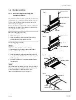
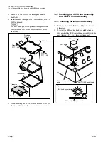
11. Disconnect the connectors (CN2, CN3, CN4, CN6)
from the VR-277 board.
12. Remove the two screws and hexagonal supports, and
remove the VR-277 board.
Hexagon supports
VR-277 board
B2.6
x
5
CN3
CN6
CN2
CN4
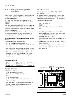
1-7. Replacing the LCD Unit
9.
Remove the screw.
10. Hold the two PWB holders using a long nose pliers as
shown in Fig. and remove the MPU-124 board by
holding it up.
n
Be careful not to damage the printed foil pattern of the
MPU-124 board with the tip of a long nose plier.
PWB holders
PWB holder
MPU-124 board
MPU-124
board
Fig.1
B2.6
x
5
Long nose pliers
Содержание RM-B750
Страница 1: ...REMOTE CONTROL UNIT RM B750 MAINTENANCE MANUAL 1st Edition Revised 1 Serial No 100001 and Higher ...
Страница 24: ......
Страница 48: ......
Страница 75: ......
Страница 82: ......
Страница 86: ......
Страница 92: ......
Страница 93: ......
Страница 94: ...Printed in Japan Sony Corporation 2005 1 16 B P Company 2002 RM B750 SY J E 9 967 994 02 ...


