5
display is a type of D-sub 15 pin, be sure to use 5BNC
- D-sub 15 pin conversion cable.
Composite input signals of channels 1 through 6
selected by the crosspoint button are converted
internally to the component video signals and output.
At the same time, input signal also output from the
VIDEO output terminal, directly.
Y R-Y B-Y input of channels 5 and 6, and RGB input
of channels 7 through 10 are not converted, but output
as they are.
The summary of signal path are indicated in below.
• When inputting only composite signals to channels 1
through 6
* The same video signal is output from RGB/Y R-Y
B-Y and VIDEO output terminals.
• When component signals and composite signals are
connected to channels 5 and 6 at the same time.
*Input signals of each are output as they are.
When there are both component and composite
signal outputs in DVD, etc. and when they are input
at the same time, these signals can be output to
several equipment such as a projector (component
signal) and monitor (composite signal).
The component signals and RGB signals input to the
channels 5 through 10 are not converted and output to
a VIDEO output terminal.
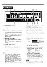
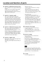
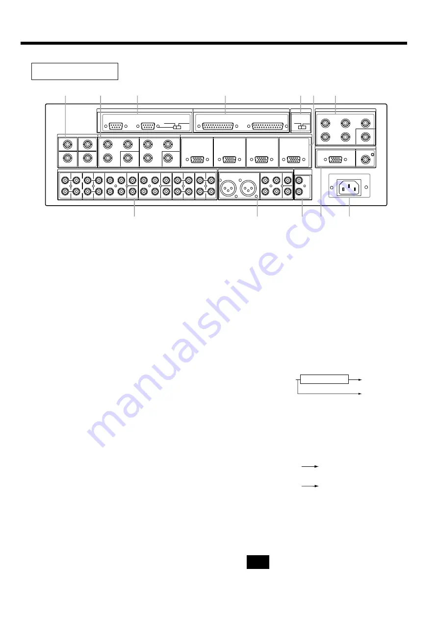
Rear panel
1
VIDEO INPUT terminals
These are composite video input terminals of channels
1 through 4.
2
COMPONENT/VIDEO INPUT terminals
These are video input terminals of channels 5 and 6.
These input composite signal and component signal of
DVD etc.
For operation of simultaneous input of component and
composite signals, please refer to
5
OUTPUT 1
terminals (Video).
3
RGB INPUT terminals
These are RGB video input terminals of channels 7
through 10.
For the signal of a computer, etc. (15k RGB cannot be
accepted.)
4
AUDIO INPUT terminals
These are audio input terminals.
Channels 5 and 6 correspond to 5.1 channel surround.
In case of stereo input through channels 5 and 6,
connect them to FRONT L and R terminals.
For channels other than 5 and 6, only stereo input is
available.
5
OUTPUT 1 terminals (Video)
These are RGB/Y R-Y B-Y output terminal and
composite video branch output terminal.
These output video signals of the INPUT channel
selected by the OUTPUT 1 crosspoint.
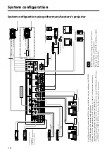
When Sony's projector is connected, connect OUT-
PUT 1 with INPUT A terminal of the projector, and
plasma display is connected; connect it to INPUT 1
terminal of a plasma display.
In case of the input terminal of the projector or plasma
COMPOSITE SIGNAL
INPUT
VIDEO
OUTPUT TERMINAL
RGB/Y R-Y B-Y
OUTPUT TERMINAL
SIGNAL CONVERT
Note
COMPOSITE SIGNAL
INPUT
VIDEO
OUTPUT TERMINAL
RGB/Y R-Y B-Y
OUTPUT TERMINAL
COMPOSITE SIGNAL
INPUT
6
RS-232C
OUTPUT 1
CONTROL
OUTPUT 2
CONTROL
REMOTE
PARALLEL I/O
IN
OUT
VIDEO INPUT
1
3
4
2
VIDEO
5
6
C
B
/
B -Y
Y
C
R
/
R -Y
C
R
/
R -Y
C
B
/
B -Y
Y
VIDEO
7
8
9
10
OUTPUT2 MODE
PROJECTOR
SYNC / HD
B/B - Y
G/Y
R/R - Y
OUTPUT 1
MONITOR
VD
VIDEO
OUTPUT 2 / MONITOR
RGB/ Y R- Y B- Y
VIDEO
~
AC IN
OUTPUT 2
/MONITOR
L
R
OUTPUT 1
L
R
L
R
CENTER
WOOFER
REAR
FRONT
7
8
9
10
L
R
L
R
1
2
5
WOOFER
REAR
FRONT
CENTER
WOOFER
REAR
FRONT
CENTER
3
4
R
L
6
AUDIO INPUT
COMPONENT/ VIDEO INPUT
RGB INPUT
1
4
2
!¡
!º
9
7
8 6
!™
5
3


