11
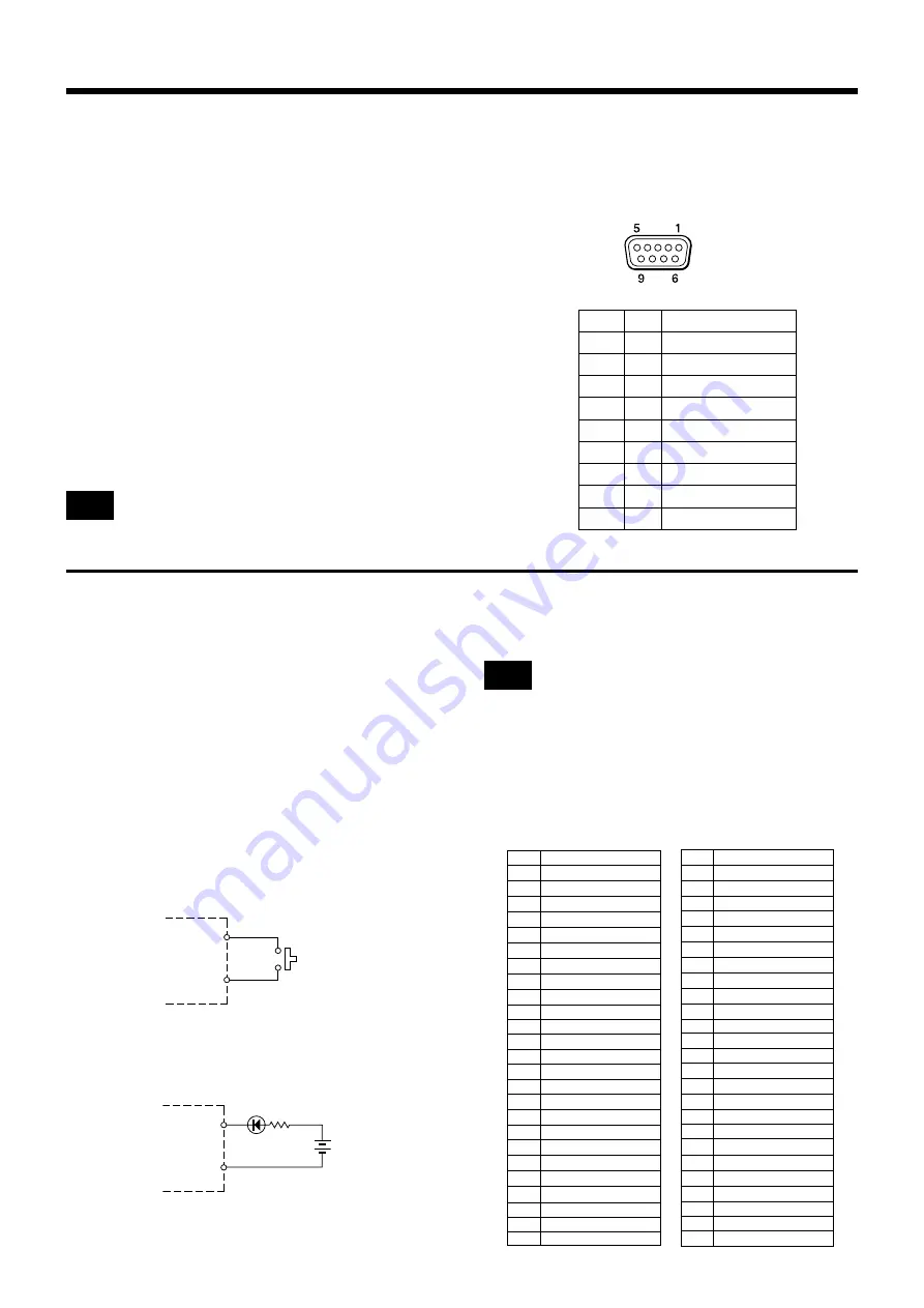
RS-232C terminal
When the OUTPUT 2 CONTROL/REMOTE switch is set
to REMOTE, this unit is able to control by external control-
ler.
The specifications are as follows
RS-232C : 9 pin D-sub (male, with inch type screws)
Electrical Spec. : Based on the RS-232C standard
Recommended cable: Multi-core shielded cable for
data communication
Cable length : Less than 15 meters
Communication format
Baud rate
: 9600 bps
Bit length
: 8 bits
Stop bit
: 1 bit
Parity
: ODD
Use the null modem cable when connecting this unit with
computer.
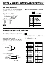
The parallel input and output terminals are those for remote
control by connecting a simple circuit to the outside of this
unit.
By shorting the input terminal to GND for 100 msec or
more, the crosspoint can be selected.
The output terminal is open collector output, the LED etc.
displays the setting condition of the crosspoint of this unit.
How to Control This Unit from External Controller
(9 pin D-sub, male)
•Connect the right one of two RS-232C terminals.
Input terminals
(Nos. 2 through 12)
(Nos.14 through 24)
GND
(Nos. 1, 13 and 25)
<
Names and function of I/O terminal
>
• For external switches, be sure to use non-lock type, such
as tactile type switch.
• Use a cable of less than 50 m long.
<Example of Input Circuit>
<Example of Output Circuit>
Output terminals
(Nos.2 through 12)
(Nos. 14 through 24)
12V MAX
20mA MAX
N
GND
(Nos. 1, 13 and 25)
Parallel Input/Output terminal
PVS-R102
PVS-R102
Note
Note
Pin No. Function
1
GND
2
crosspoint 1 - 1
3
crosspoint 1 - 2
4
crosspoint 1 - 3
5
crosspoint 1 - 4
6
crosspoint 1 - 5
7
crosspoint 1 - 6
8
crosspoint 1 - 7
9
crosspoint 1 - 8
10
crosspoint 1 - 9
11
crosspoint 1 - 10
12
crosspoint 1 - OFF
13
GND
14
crosspoint 2 - 1
15
crosspoint 2 - 2
16
crosspoint 2 - 3
17
crosspoint 2 - 4
18
crosspoint 2 - 5
19
crosspoint 2 - 6
20
crosspoint 2 - 7
21
crosspoint 2 - 8
22
crosspoint 2 - 9
23
crosspoint 2 - 10
24
crosspoint 2 - OFF
25
GND
[ INPUT ]
Pin No. Function
1
GND
2
tally1 - 1
3
tally1 - 2
4
tally1 - 3
5
tally1 - 4
6
tally1 - 5
7
tally1 - 6
8
tally1 - 7
9
tally1 - 8
10
tally1 - 9
11
tally1 - 10
12
tally1 - 0FF
13
GND
14
tally2 - 1
15
tally2 - 2
16
tally2 - 3
17
tally2 - 4
18
tally2 - 5
19
tally2 - 6
20
tally2 - 7
21
tally2 - 8
22
tally2 - 9
23
tally2 - 10
24
tally2 - 0FF
25
GND
[ OUTPUT ]
1 FG Frame GND
2 RD Receive Data
3 TD Transmitted Data
4 ER Data Terminal Ready
5 SG Signal GND
6 DR Data Set Ready
7 RS Request to Send
8 CS Clear to Send
9 N.C Non Connection
Pin No. Signal Function


