


1-7 (E)
PMW-EX1R
.
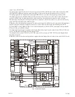
Audio Codec (IC202, IC203)
The analog audio signal from the AU-326 board is connected to IC202 and IC203 that are the Audio Codec (PGA, ADC,
DSP, Digital IF, headphones ampli
fi
er, speaker ampli
fi
er are built on one chip and the parameters are set with I
2
C).
The analog signal after level adjustment by the Input TRIM (PGA) is converted to the digital signal with the ADC.
The digital signal receives the [Wind Filter] (on/off) processing of the Audio Level control, AGC Limiter and Internal
mic from the DSP. After the audio signal receives these processing, the digital signal is output for audio recording.
Playback output (including EE) is the digital signal that is connected to Audio Codec where it is converted to the analog
signal with DAC and output to the ASW-68 board.
Furthermore, the audio signal that is processed for audio monitoring in the ASW-68 board is connected to the headphones
ampli
fi
er and speaker ampli
fi
er through the monitor level control from the IN2LP input and IN2RP input of IC202.
From the DPR-311 board, BEEP (IC600) is level-controlled internally by IN2LN (IC202), and output to the speaker HP.
.
FPGA (IC1300) on the DPR-311 Board
The digital signal output signal is supplied to the Display Block (Base band) from the Audio Codec. FPGA (IC1300) also
receives the playback output signal from the Display Block.
The playback system selects CH1/CH2 or CH3/CH4, connects EE, and connects TEST TONE from the Display Block
depending on the data.
Furthermore, FPGA divides the clock signal that is supplied from the Display Block to Audio Codec on the DAP-41 board.
INT/EXT1,INT/EXT2
MIC/LINE/+48V-1,
MIC/LINE/+48V-2,
WIND FILTER1,
WIND FILTER2
COPY1to2, LINK2to1, LINK1to2
MA-183
AXM-42
VIF-46
KSW
-55
HN-361
DPR-31
1
NH-360
AU-326
LED-491
IC202(1/2)
IC205,206,207,208
+48V /MIC / LINE -2
+48V
CLOCK DIV
(1fs,64fs,256fs)
IC1300
LINE 3/4
IC600
IC202(2/2)
IC204 (1/2)
IC204 (2/2)
IC200,
IC202 (1/2)
IC201,
IC202 (2/2)
ASW-68
DAP-41
MUTE
MONI1-1,2-1,
MONI2-2,2-1
IC203, 205
DPR-311
INT MIC1
with
HEAD AMP
+10dB
INT MIC2
with
HEAD AMP
+10dB
MIC/LINE
1
(XLR)
MIC/LINE
2
(XLR)
AV Monitor
Out 1
(Line Out1)
AV Monitor
Out 2
(Line Out2)
HP Out
(PHONE
MINI)
SPEAKER
PGA
GAIN
PGA
GAIN
DIGITAL
AUDIO IF
DIGITAL
AUDIO IF
A/D
FIL
LVL
AGC/
LIM
PGA
GAIN
PGA
GAIN
A/D
FIL
LVL
AGC/
LIM
GPIO
BAL
AMP
BAL
AMP
SEL/
MIX1
IC203
BAL
AMP
BAL
AMP
IC200
WIND FILTER1
WIND FILTER2
INT/EXT 1
+48V
+48V /MIC / LINE -1
0/12dB-1
Control
with PGA
IC202
INT/EXT 2
0/12dB-2
Control
with PGA
SEL/
MIX2
MUTE
MUTE
MUTE
MUTE
AMP
AMP
D/A
AMP
AMP
AMP
MONITOR LEVEL
IC202
IC203
LINK 2 1
COPY1to 2
LINK 1 2
FIL
ATT
FIL
ATT
FPGA
Digital Audio 1
CLOCK DIV
(1fs,64fs,256fs)
Digital Audio 2
Digital Audio
1/2 , 3/4
CONTROL
(T-one)
I2C
I2C
IC203
+
MIX
AMP
SEL/
MIX1
MONI 1-1
MONI 2-1
MONI2-2
MONI1-2
SEL/
MIX2
IN2LP(L)
IN2RP(R)
IN2LN
I2C MPX
(DEVICE CONTROL)
IC201
PWR or
DET
GPIO
CONTROL
(T-one)
IC600
IC600
BEEP
(T-one)
CN-3273
Fig. 1. Audio block diagram
Содержание PMW-EX1R
Страница 1: ...SOLID STATE MEMORY CAMCORDER PMW EX1R WIDE CONVERSION LENS VCL EX0877 SERVICE MANUAL 1st Edition ...
Страница 4: ......
Страница 8: ......
Страница 106: ......
Страница 107: ......