background image

35

Handling Discs

Chapter

  Chapt

er

 3

  Rec

o

rd

ing and

 P

la

y

bac

k

3

Recording and Playback

Handling Discs

Discs Used for Recording and 
Playback

This unit uses the following disc for recording and 
playback:

• PFD23 Professional Disc

 1)

 (capacity 23.3 GB)

• PFD23A (capacity 23.3 GB)

1) Professional Disc is a trademark of Sony Corporation.

It is not possible to use the following discs for recording or 
playback:
• Blu-ray Disc
• Professional Disc for Data

Notes on Handling

Handling

The Professional Disc is housed in a cartridge, and is 
designed to allow handling free of risk from dust or 
fingerprints. However, if the cartridge is subjected to a 
severe shock, for example by dropping it, this can result in 
damage or scratching of the disc. If the disc is scratched, it 
may be impossible to record video/audio, or to play back 
the content recorded on the disc. The discs should be 
handled and stored carefully.
• Do not touch the surface of the disc itself within the 

cartridge.

• Deliberately opening the shutter may cause damage.
• Do not disassemble the cartridge.
• The supplied adhesive labels are recommended for 

indexing discs. Apply the label in the correct position.

Storage

• Do not store discs where they may be subjected to direct 

sunlight, or in other places where the temperature or 
humidity is high.

• Do not leave cartridges where dust may get inside.
• Store cartridges in their cases.

Care of the discs

• Remove dust and dirt on the outside of a cartridge using 

a soft dry cloth.

• If condensation forms, allow ample time to dry before 

use.

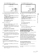
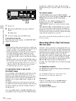
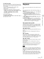
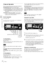
Write-Protecting Discs

To protect the content recorded on the disc from accidental 
erasure, move the Write Inhibit tab on the lower surface of 
the disc in the direction of the arrow, as shown in the 
following figure.

You can also write protect individual clips. For details, see 

“Locking (Write-protecting) Clips” (page 48)

.

Note

SAV

E

SAVE

SAVE

Lower surface of the disc

Write Inhibit tab

Slide in the direction of the arrow

Write Inhibit tab settings

Recording enabled

Recording disabled

Содержание PDW-F30

Страница 1: ...3 990 977 16 1 Professional Disc Recorder Operating Instructions Before operating the unit please read this manual thoroughly and retain it for future reference PDW F30 2006 Sony Corporation ...

Страница 2: ... of fire or electric shock do not expose this apparatus to rain or moisture To avoid electrical shock do not open the cabinet Refer servicing to qualified personnel only THIS APPARATUS MUST BE EARTHED CAUTION The apparatus shall not be exposed to dripping or splashing No objects filled with liquids such as vases shall be placed on the apparatus CAUTION The unit is not disconnected from the AC powe...

Страница 3: ... IEC60825 1 2001 This label is located on the top panel of the drive unit Denna etikett finns på ovansidan av driftenheten Denne mærkat sidder på drevenhedens øverste panel Tämä kyltti sijaitsee ajurilaitteen yläpinnalla Dette merket er plassert på oversiden av driverenheten CAUTION The use of optical instruments with this product will increase eye hazard CAUTION Use of controls or adjustments or ...

Страница 4: ...ow Voltage Directive issued by the Commission of the European Community Compliance with these directives implies conformity to the following European standards EN60065 Product Safety EN55103 1 Electromagnetic Interference Emission EN55103 2 Electromagnetic Susceptibility Immunity This product is intended for use in the following Electromagnetic Environment s E1 residential E2 commercial and light ...

Страница 5: ...Editing System AV C Connection 25 Connections for Cut Editing 25 Editing Control Unit Settings 26 Remote Control Unit Settings 26 Setup 27 Setting the Date and Time 27 Adjusting the Brightness of the LCD Panel 27 24P 23 98P Mode Settings 29 Selecting the Playback Mode 23 98PsF or 2 3 Pulldown 29 Output Signals in 24P 23 98P Mode 30 Playback in 24P 23 98P 2 3 Pulldown Mode 31 Superimposed Text Info...

Страница 6: ...hapter 4 Scene Selection Overview 52 Assigning Clip Titles 55 Assigning User Defined Clip and Clip List Names 55 Creating Clip Lists 57 Including Clips Selected in the Thumbnail Screen in the Clip List 57 Quick Scene Selection Adding Sub Clips During Recording Playback or Search 60 Editing Clip Lists 62 Basic Operations 62 Reordering Sub Clips 62 Modifying the In and Out Points of Sub Clips Trimmi...

Страница 7: ...de Over FAM Connections 77 Chapter 6 Menus Function Menu 78 Function Menu Operations 78 Function Menu Settings 78 System Menu 80 Displaying the Setup and Disc Menus 80 Setup Menu 80 Setup Menu Items 82 Setup Menu Operations 90 Disc Menu 93 Disc Menu Operations 94 Chapter 7 Using Option Boards Option Boards for Enhanced Functionality 96 Using the PDBK 101 Network Board Gigabit Ethernet 96 Computer ...

Страница 8: ...r 99 Troubleshooting 100 Alarms 100 Error Messages 107 To Eject Discs With the Unit Powered Off 107 About i LINK 107 Specifications 108 Using UMID Data 111 MPEG 4 Visual Patent Portfolio License 113 MPEG 2 Video Patent Portfolio License 113 Glossary 114 Index 115 ...

Страница 9: ...encies The unit can play back five different frame frequencies 1080 59 94i displayed as 60I 50i displayed as 50I 29 97PsF displayed as 30P 25PsF and 23 98PsF The unit features a standard 2 3 pulldown function and can output 60I when playing back a disc recorded in 23 98PsF HD downconvert function An HD downconvert function enables output of SD composite component and i LINK DV signals even when th...

Страница 10: ...o display thumbnail lists on the computer screen and perform file based reads and writes 1 XDCAM allows you to record various kinds of information about the video and audio data such as the date of shooting the editor the recording format and comments This data can be used in the following ways The supplied PDZ 1 Proxy Browsing Software can add titles comments and other text data to discs and clip...

Страница 11: ...tible files for recording by this unit When you record to discs you can select the appropriate video bitrate for your application from three video bitrate modes 35 Mbps HQ high quality mode 25 Mbps SP standard mode and 18 Mbps LP long play mode You can select 2 channel or 4 channel mode audio but only channels 1 and 2 are recorded 1 HDV and are trademarks of Sony Corporation and Victor Company of ...

Страница 12: ...nection If the on standby switch is pressed while this indicator is lit the unit waits until access to the disc is completed before switching to the standby state PHONES VAR JOG MARK1 MENU PAGE DISPLAY SUB CLIP F1 F5 F4 F3 F2 SHIFT CLIP MENU ESSENCE MARK SET THUMB NAIL RESET OUT IN MARK2 SHUTTLE TOP KEY INHI EXPAND CHAPTER F REV F FWD END PREV NEXT PLAY STOP STANDBY TS REC EJECT CH 1 CH 2 CH 3 CH ...

Страница 13: ...hen pressed alone and as a CLIP MENU button when pressed together with the SHIFT button SUB CLIP button Press this button turning it on to perform playback of a clip list A clip list selection screen appears To play back the clips in the order they were recorded press this button again turning it off The clip list selection screen disappears This button does not light and pressing it has no effect...

Страница 14: ... press of this button turns key operation inhibit mode on or off d PAGE button This displays the function menu if it is not already visible The most recently accessed page appears If the function menu is visible this button switches between the function menu pages HOME P1 e Monitor video display section This displays monitor video and the system menu You can press the DISPLAY button to switch the ...

Страница 15: ... 0 dB the red indicator bar at the top lights k Audio format During playback this displays the number of recording audio channels on the disc and the number of quantization bits During display of E E1 video this displays 2CH 16BIT two channels 16 bits or 4CH 16BIT four channels 16 bits according to the setting of AUDIO CONTROL REC MODE in the setup menu see page 89 Always displays 4CH 16BIT when t...

Страница 16: ... In or Out point is set when you press the SET button with the IN or OUT button held down The In or Out point setting is deleted when you press the RESET button with the IN or OUT button held down b M MARK1 button and m MARK2 button When the setup or disc menu is visible use these buttons to change menu settings When the THUMBNAIL button is lit you can use these for thumbnail selection During reco...

Страница 17: ... PREV button when pressed alone and as a TOP button when pressed together with the SHIFT button PREV button Press this button turning it on to jump to the first frame of the current clip or the previous REC START essence mark 1 When pressed at the first frame of the current clip this button jumps to the first frame of the previous clip if it exists TOP button Press this button to jump to the first...

Страница 18: ...together with the PLAY button to start recording Recording starts on the unrecorded part of the disc Press the STOP button to stop recording A clip is created from the recorded section This button is enabled when you record TS input signals when the PDBK 102 MPEG TS Input Output Board is installed or the signals of the internal signal generator Rear Panel 1 Analog video signal output section a COM...

Страница 19: ...ndby state the on standby indicator lights red Before turning the main power off always check to be sure that the unit is in the standby state and then push the main power switch to the a side 4 External device connection section a RS232C serial interface connector D sub 9 pin male Connect a computer or other device with a serial interface to control this unit from that device When you use this co...

Страница 20: ...or of the main unit and press the keys and setting pad If you want to disable control of this unit from the remote commander set INTERFACE SELECT WIRELESS RMT in the setup menu to DISABLE see page 90 a Setting pad Positions on the pad correspond to functions of the main unit as follows Press the top side M MARK1 button Press the bottom side m MARK2 button Press the left side IN button Press the ri...

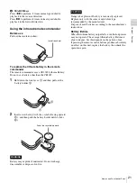
Страница 21: ...th the symbol facing upward 1 and then push the battery holder until it clicks 2 Battery may explode if mistreated Do not recharge disassemble or dispose of in fire Danger of explosion if battery is incorrectly replaced Replace only with the same or equivalent type recommended by the manufacturer Dispose of used batteries according to the manufacturer s instructions Battery lifetime When the lithi...

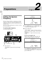
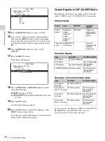
Страница 22: ...ave processing finishes If you have selected 60I or 30P When you press the SET button with 60I or 30P selected in step 2 the following screen appears Press the M MARK1 and m MARK2 buttons to select UC for areas outside Japan or J for Japan then press the SET button PHONES VAR JOG MARK1 MENU PAGE DISPLAY SUB CLIP F1 F5 F4 F3 F2 SHIFT CLIP MENU ESSENCE MARK SET THUMB NAIL RESET OUT IN MARK2 SHUTTLE ...

Страница 23: ...ame mode NDF on page P1 of the function menu see page 79 Connections and Settings Production of some of the peripherals and related devices described in this chapter has been discontinued For advice about choosing devices please contact your Sony dealer or a Sony sales representative Connecting an External Monitor You can connect a video monitor to this unit s video output connectors or to the MON...

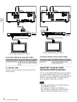
Страница 24: ...driver This unit s S400 connector has 6 pins Check the number of pins on the i LINK connector of your Connection method Connection cables not supplied Component Y PB PR D Sub 15 pin analog component cable phono plug stereo miniplug cable POWER COMPOSITE OUT AUDIO MONITOR AUDIO OUTPUT 1 3 2 4 R L RS232C REMOTE 9P S400 AC IN MONITOR MONITOR AUDIO MONITOR PDW F30 this unit MEU WX2 Multi Format Engine...

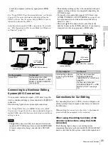
Страница 25: ...he audio mode the factory default is 2ch This unit s S400 connector has 6 pins Check the number of pins on the i LINK connector of your laptop computer and use an appropriate i LINK cable Connections for Cut Editing By connecting this unit to a VTR you can configure a cut editing system Some example connections are shown in the following When making the connections also refer to the manuals provid...

Страница 26: ... MONITOR AUDIO OUTPUT 1 3 2 4 R L RS232C REMOTE 9P S400 AC IN MONITOR MONITOR AUDIO i LINK VIDEO OUT 3 SUPER S400 COMPOSITE OUT AUDIO MONITOR To analog audio input connector PDW F30 this unit player 1 2 Phono plug stereo miniplug cable not supplied 3 Phono plug cable not supplied To composite video input connector DSR 2000A 2000AP recorder SD video monitor SD video monitor To composite video input...

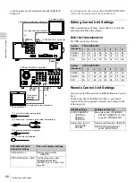
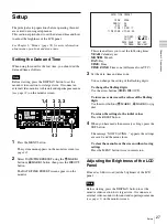
Страница 27: ...ncrease or decrease the values of the flashing digits Use the arrow buttons M MARK1 m MARK2 or jog dial To return the settings to the initial values Press the RESET button 4 When you have made the necessary settings press the SET button The message NOW SAVING appears the settings are saved and the menu closes To clear the menu from the screen without saving settings Press the MENU button twice in ...

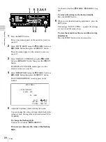
Страница 28: ...increase or decrease the values of the flashing digits Use the arrow buttons M MARK1 m MARK2 or jog dial To return the settings to the factory defaults Press the RESET button 6 When you are finished making adjustments press the SET button The message NOW SAVING appears the settings are saved and the menu closes To clear the menu from the screen without saving adjustments Press the MENU button twic...

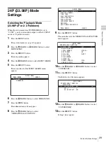
Страница 29: ...r 8 Press the M MARK1 button to select OPERATIONAL FUNCTION 9 Press the OUT button The second level of the OPERATIONAL FUNCTION menu appears 10Press the M MARK1 or m MARK2 button to select SYSTEM SEL 11Press the OUT button The third level of the menu appears 12Press the M MARK1 or m MARK2 button to select SYSTEM FREQ 13Press the OUT button Setting values appear SETUP MENU MENU GRADE BASIC ENHANCED...

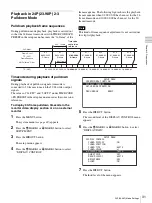
Страница 30: ...nals Timecode display Timecode in remote timecode mode See the optional 9pin Manual PDW Series PROTOCOL OF REMOTE 9 pin CONNECTOR for more information about remote timecode mode SETUP MENU OPERATIONAL FUNCTION SYSTEM SEL SYSTEM FREQ 601 60I 50I 30P 25P 23 98P SETUP MENU OPERATIONAL FUNCTION SYSTEM SEL 23 9P OUTPUT PsF 23 98PsF 2 3 PULL DOWN Output Type 23 98PsF 2 3 PULL DOWN Output signals Composi...

Страница 31: ... or on an external monitor 1 Press the MENU button The system menu see page 80 appears 2 Press the M MARK1 or m MARK2 button to select SETUP MENU 3 Press the OUT button The setup menu appears 4 Press the M MARK1 or m MARK2 button to select DISPLAY CONTROL 5 Press the OUT button The second level of the DISPLAY CONTROL menu appears 6 Press the M MARK1 or m MARK2 button to select DISPLAY INFO 7 Press...

Страница 32: ... on the LCD panel of this unit but do not display it on an external video monitor connected to this unit Even when ON is selected you can forcibly turn off the superimposition of character information in HD output by setting the SETUP MENU DISPLAY CONTROL HD CHARA item Adjusting the text display You can use the items in the DISPLAY CONTROL setup menu to specify the position size and type of superi...

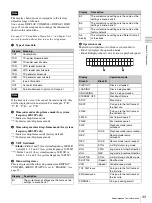
Страница 33: ...ta TCR TC reader timecode data UBR TC reader user bits data TCR VITC reader timecode UBR VITC reader user bits data TCG TC generator timecode UBG TC generator user bits data IN In point time data OUT Out point time data DUR Duration between In point and Out point Note Display Description B1 The current menu settings are the same as the settings in menu bank 1 B2 The current menu settings are the s...

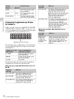
Страница 34: ...ation Meaning INT PRST FREE The internal timecode generator is operating in FREE RUN mode INT PRST REC The internal timecode generator is operating in REC RUN mode INT REGEN T U The internal timecode generator is in synchronization with the playback timecode LTC read from disc Display Operation mode Block A Block B T C R P L A Y 0 0 0 4 4 7 0 7 L O C K I N V A 1 3 4 2 T C S Supplementary status in...

Страница 35: ... touch the surface of the disc itself within the cartridge Deliberately opening the shutter may cause damage Do not disassemble the cartridge The supplied adhesive labels are recommended for indexing discs Apply the label in the correct position Storage Do not store discs where they may be subjected to direct sunlight or in other places where the temperature or humidity is high Do not leave cartri...

Страница 36: ...formatting another disc When the message FORMAT COMPLETED appears press the EJECT button to eject the disc Insert the next disc to format and press the SET button when the message QUICK FORMAT OK appears 7 Press the MENU button to clear the menu from the screen Handling of Discs When Recording Does Not End Normally Salvage Functions Recording processing does not end normally if for example the POW...

Страница 37: ...rom 4 to 6 seconds of data before the interruption of recording You are prompted to execute a full salvage every time you insert a disc that has not been salvaged or power the unit on with such as disc loaded No recording is possible on discs containing clips that have not been salvaged although it is possible to play back the normally recorded sections Recording becomes possible if you perform a ...

Страница 38: ...t rate compression method by setting OPERATIONAL FUNCTION REC FORMAT in the setup menu to one of the following To set the audio recording format Set AUDIO CONTROL REC MODE in the setup menu to one of the following Recording Timecode and User Bit Values There are the following two ways of recording timecode Internal Preset mode This records the output of the internal timecode generator set beforeha...

Страница 39: ...ernal Preset see page 38 The UB PRESET MODE screen appears 3 Use the arrow buttons and the RESET button to set the user bits IN button or OUT button Select the digit to change it flashes M MARK1 button or m MARK2 button Change the value of the selected digit RESET button Reset all digits to 0 Settings are made in hexadecimal 0 1 2 8 9 A B E F To cancel the user bits setting Press the MENU button 4...

Страница 40: ... shot marks A SHOT MARK1 essence mark or SHOT MARK2 essence mark is set if you hold down the M MARK1 or m MARK2 button and press the SET button during recording If the unit is set up to display superimposed text information see page 32 SHOTMARK1 or SHOTMARK2 appears every time you set an essence mark When SHOT MARK1 or SHOT MARK2 essence marks are set you can search for the shot marks by displayin...

Страница 41: ...ayback start position Although this unit uses optical discs it is designed to offer the most convenient features of tape playback by VTRs One of these is the playback start position which works in the same way as tape as described below After playback stop The unit stops at the position where the STOP button was pressed Press the PLAY button to resume playback at the stop position After recording ...

Страница 42: ... the SET button To erase or change essence marks use the supplied PDZ 1 Proxy Browsing Software Playback in jog mode In jog mode you can control the speed of playback by the speed of turning the jog dial The playback speed range is 1 to 2 times normal speed To carry out playback in jog mode proceed as follows 1 Press the JOG button turning it on 2 Turn the jog dial in the desired direction at the ...

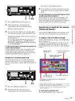
Страница 43: ...yback by pressing the PLAY and VAR buttons alternately Searching for Clips With Thumbnails Thumbnail Search You can display thumbnail images index pictures of all clips on the disc and use them to cue up a desired clip To display a list of thumbnail images With the SUB CLIP button off press the THUMBNAIL button turning it on A list appears showing thumbnails of 12 clips on the disc including the c...

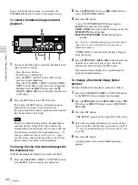
Страница 44: ...s the M MARK1 button or m MARK2 button to select CLIP INFORMATION 3 Press the SET button A list of CLIP INFORMATION items appears DATE Date and time of recording TIME CODE Timecode of the first frame in the clip DURATION Recording time SEQUENCE NUMBER Thumbnail sequence number See To select a thumbnail image and start playback page 44 for more information about sequence thumbnail numbers TIME CODE...

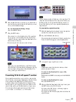
Страница 45: ... scene You can repeat the expand operation up to three times t 12 blocks t 144 blocks t 1 728 blocks The maximum number of blocks may be larger than 1728 when the recorded duration of the clip is short In this case the frame interval of expanded thumbnails is fixed at 1 frame This allows you to view expanded thumbnails at equal intervals To execute the expand function 1 With the thumbnail list dis...

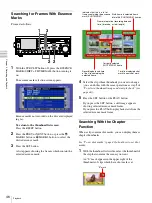
Страница 46: ...e PLAY button playback starts from the selected essence mark frame Searching With the Chapter Function When a clip contains shot marks you can display them as chapter thumbnails See To set shot marks page 40 about how to set shot marks 1 With the thumbnail list visible select the thumbnail of the clip that contains the scenes you want An S mark appears in the upper right of the thumbnails of clips...

Страница 47: ...ppears in the upper left of the screen 3 Select the thumbnail image of the shot mark position to delete 4 Press the SET button A message appears asking for confirmation of the deletion 5 Press OK to execute the deletion or CANCEL to cancel it and then press the SET button Clip List Playback You can play back clips in the same order as in a clip list created using the scene selection function See C...

Страница 48: ... sub clip finishes it resumes from the start of the clip list repeatedly playing from the first through the last sub clip in the clip list Repeat playback begins the unit is powered on if it is powered on with a disc loaded and OPERATIONAL FUNCTION REPEAT MODE in the setup menu set to ON Clip list playback starts from the first sub clip in the clip list To start repeat playback from the device con...

Страница 49: ...ed clip to show that it is locked Locked clips cannot be deleted or set the thumbnail image index picture and so on Unlock the clip if you want to perform any of these operations To lock clips with a shortcut operation After carrying out step 2 in the procedure press the STOP button with the SHIFT button held down shortcut operation You can lock clips without displaying the CLIP MENU To unlock cli...

Страница 50: ...nding on whether the target clip is referenced in a clip list When the target clip is not referenced in a clip list DELETE CLIP When the target clip is referenced in a clip list DELETE CLIP CLIP LIST The clip list that references the clip will also be deleted To cancel the deletion and return to the CLIP MENU Select CANCEL and then press the SET button Press the RESET or MENU button 5 Use the V MA...

Страница 51: ...he clips on the disc appear 2 Press the MENU button The CLIP menu appears 3 Use the V MARK1 button to select CLIP INFORMATION and then press the SET button A sub menu appears 4 Use the v MARK2 button to select SEQUENCE NUMBER and then press the SET button As shown in the following figure sequential numbers are assigned to thumbnails ...

Страница 52: ...ne selection function you create clip lists edit data The clips themselves are not changed so you can repeat the operation as often as you like Clip lists created with the scene selection function can be played back on this unit The scene selection function makes it easy to carry out operations such as adding material in clip units adding parts of clips adding by chapter reordering the playback or...

Страница 53: ...PLAY STOP STANDBY EJECT CH 1 CH 2 CH 3 CH 4 NETWORK LOCAL REMOTE ACCESS LEVEL TS REC PRESET PB Record material or insert disc containing recorded material into this unit PDW F330 F350 To edit a clip list on the disc Load a clip list see page 67 Including a sub clip in the current clip list see page 57 Reordering sub clips see page 62 Changing sub clip In and Out points trimming see page 63 Deletin...

Страница 54: ...rt of clip 3 Therefore when clip list E0001 is played back clip 4 is played after clip 2 and then the part of clip 3 shown in gray color is played Clip list editing current clip list To edit a clip lists you need to load the clip from the disc into the internal unit memory The clip list which is currently loaded into the unit memory is called the current clip list The current clip list is always t...

Страница 55: ...een appears PREFIX Prefix up to 5 alphanumeric characters and symbols NUMERIC Initial value of the number 00001 to 99999 2 Enter the prefix and initial number To select the item to set and the character to set it flashes Use the arrow buttons To select a character to enter at the selected position Turn the jog dial To return the settings to the factory defaults Press the RESET button 3 When you ar...

Страница 56: ...nge clip list names execute the Rename command for a file in the Edit folder with the extension SMI The extension SMI cannot be changed To check clip names Press the THUMBNAIL button to display the thumbnail screen and select the clip whose name you want to check The name of the selected clip appears at the upper left of the screen However when a title has been assigned to a clip display of the ti...

Страница 57: ... to use while viewing the video quick scene selection Before starting Insert a disc containing recorded clips into the unit Including Clips Selected in the Thumbnail Screen in the Clip List Proceed as follows 1 With the SUB CLIP button unlit press the THUMBNAIL button lighting it Thumbnails of the clips on the disc appear In the following description this is referred to as the thumbnail screen PHO...

Страница 58: ...te and time when the clip list was created or last modified TITLE Title assigned to the clip list NAME Name of the clip list or a user defined name You can use the supplied PDZ 1 Proxy Browsing Software to assign titles to clip lists 4 Use the M MARK1 or m MARK2 button to select a clip list number such as E0001 and then press the SET button This returns to the thumbnail screen 5 Press the SUB CLIP...

Страница 59: ...XT button Moves the cursor to the previous or next sub clip Press the PREV or NEXT button with the SHIFT button held down Moves the cursor to the first or last sub clip Press M MARK1 or m MARK2 button Moves to the 4th previous or 4th next sub clip 11With the SHIFT button held down press the SET button All the clips selected in step 8 are added to the current clip list as sub clips and the scene se...

Страница 60: ...included as a sub clip 3 Save the current clip list to disc For details see Saving the Current Clip List to Disc page 65 Even if you select several thumbnails they are added to the clip list as one continuous sub clip To add sub clips using the chapter function The chapter function allows a thumbnail to be displayed for each shot mark recorded within a clip For details see Chapter 3 Searching for ...

Страница 61: ...n image of the In point is cued up if you hold down the IN button and press the PREV button or NEXT button An image of the Out point is cued up if you hold down the OUT button and press the PREV button or NEXT button To check the duration Hold down the IN button and the OUT button at the same time The duration appears on the screen To reset an In point or Out point With the IN button or OUT button...

Страница 62: ...wing pages Reordering sub clips Page 62 Trimming sub clips Page 63 Deleting sub clips Page 64 Setting the timecode Page 64 7 Save the edited current clip list to disc For details see Saving the Current Clip List to Disc page 65 Reordering Sub Clips Proceed as follows 1 Carry out steps 1 to 5 of the procedure in Basic Operations see page 62 select MOVE in step 2 The I shaped cursor indicating the m...

Страница 63: ...n point or Out point of the selected sub clip 3 At the scene where you want to set a new In or Out point hold down the IN button to change the In point or the OUT button to change the Out point and press the SET button Depending on the button that you pressed a new In or Out point is set The IN and OUT indicators flash if you set an Out point with timecode smaller than the In point If this occurs ...

Страница 64: ...ist Continuous timecode is used in clip lists regardless of the timecode of the parent clips of sub clips Therefore you can set the start timecode for each clip list By default the start timecode LTC for the current clip list is set to 00 00 00 00 To set this to a different value proceed as follows 1 Carry out steps 1 to 4 of the procedure in Basic Operations see page 62 select TC PRESET in step 2...

Страница 65: ... the M MARK1 or m MARK2 button to move the cursor to SAVE CLIP LIST and then press the SET button A list of clip lists appears The date of creation or the title is displayed for each clip list NEW FILE is displayed for clip lists without any saved data To switch between title display and date of creation display Press the OUT button For details see To select the type of clip list information to di...

Страница 66: ...T button and press the SUB CLIP button Item Operation reference page CLIP INFORMATION Select the information displayed beneath thumbnails see page 67 LOAD CLIP LIST Load a clip list from the disc into the current clip list see page 67 SAVE CLIP LIST Save the current clip list to disc see page 65 DELETE CLIP LIST Delete a clip list from the disc see page 67 SORT CLIP LISTS BY You can sort the clip ...

Страница 67: ... button A list of clip lists appears see page 58 3 Use the M MARK1 or m MARK2 button to select the desired clip list and then press the SET button The selected clip list is loaded into the unit as the current clip list To display thumbnails of the loaded current clip list Press the THUMBNAIL button and SUB CLIP button turning them on If an unsaved clip list exists in current clip list memory A war...

Страница 68: ...t the type of sorting NAME Sort in ascending order by clip list name DATE Sort by date of creation with the newest clip list first 4 Press the IN button Sorting starts on LOAD CLIP LIST screen and so on Unused clip lists are excluded from the sort If you selected NAME If you selected DATE You can jump to the first clip or last clip by pressing the PREV or NEXT button with the SHIFT button held dow...

Страница 69: ...h Intel Pentium M CPU at least 1 GHz installed memory at least 512 MB Operating system Microsoft Windows XP Professional SP2 or higher Windows Vista Ultimate Business 32bit or Mac OS X v10 4 11 or higher Web browser Internet Explorer 6 0 SP1 or higher DirectX DirectX 8 1b or higher To install PDZ 1 Insert the supplied CD ROM XDCAM Application into the CD ROM drive of your computer navigate to the ...

Страница 70: ...ing figure shows the directory structure of discs visible to a remote computer This structure is not the same as the actual structure recorded on the disc a Root directory b Only when sub item NAMING FORM on the SETUP OPERATIONAL FUNCTION FILE NAMING page is set to free Note root a INDEX XML ALIAS XML b Clip Edit Sub General DISCMETA XML MEDIAPRO XML C0001 MXF C0001M01 XML C0002 MXF C0002M01 XML C...

Страница 71: ... is set to OFF With firmware version 1 1 and lower only the most recently recorded clip may be deleted With firmware version 1 5 and higher any clip may be selected and deleted e Only files which can be written by XDCAM f With firmware version 1 5 and higher when the C part of a C MXF file name is changed a C M01 XML file with the same name in the C part is also changed automatically g When a C MX...

Страница 72: ...L file with the same name in the E part is also generated automatically h When an E E01 SMI file is deleted an E M01 XML file with the same name in the E part is also deleted automatically Directories cannot be created in the Edit directory Sub directory a With firmware version 1 5 and higher the C part can be changed to a user defined name b With firmware version 1 5 and higher when the C part of...

Страница 73: ...0 File Operations in File Access Mode for Windows File access mode operating environment Operating system requirements for file operations by file access mode are as follows Computer operating system Microsoft Windows XP Professional SP2 or higher or Microsoft Windows Vista Ultimate Business 32bit Preparations Do the following on the remote computer and this unit Install the FAM driver on the remo...

Страница 74: ...ration Restrictions page 71 To eject discs from a remote computer Right click the icon representing this unit in Explorer and select Eject from the menu which appears To exit file operations Proceed as follows Do not disconnect the cable before performing steps 1 to 3 1 Do one of the following on the or icon displayed in the remote computer s taskbar Double click Right click and select Safely Remo...

Страница 75: ... item To install the FAM driver Insert the supplied CD ROM XDCAM Application into the CD ROM drive of your computer and execute the FAM Driver Mac FAM Driver 1 1 1 dmg file then follow the installation instructions For details refer to the ReadMe file contained on the CD ROM disc To check the FAM driver version Connect this unit to your computer with an i LINK cable and then with a disc loaded sta...

Страница 76: ...l drives and files on network computers If you power this unit off during an FAM connection the data transferred thus far is discarded All file operations are not possible for some types of files For details see File Operation Restrictions page 71 To eject discs from a remote computer Click the eject button to the right of the icon for this unit in the Finder or drag the icon for this unit from th...

Страница 77: ...last frame of the last clip recorded on the disc To record continuous timecode Before you start recording set TC MODE on page P1 of the function menu to REGEN Then write clip files to this unit from a connected computer or other device With PDBK 102 option board installed Before you start recording set TCG on page P1 of the function menu to INT and set TC MODE to REGEN Then write clip files to thi...

Страница 78: ...ME t P1 t HOME To clear the function menu from the screen Press the DISPLAY button The size of the monitor video section increases To change the setting of a function menu item Use the F1 to F5 buttons Press the button to the right of each setting item to change the value of the item Keep pressing the button until the value you want appears Function Menu Settings The following tables list the sett...

Страница 79: ... on for the LCD panel only Even when ON is selected you can forcibly turn off the superimposition of character information in HD output by setting the SETUP MENU DISPLAY CONTROL HD CHARA item Setting item Description F2 TC MODE timecode mode Selects whether the count value advances from a preset initial value or advances consecutively from the timecode of the last frame recorded on the disc PRESET...

Страница 80: ...ess the MENU button The system menu appears The entire system menu appears in the monitor video section and on the external monitor An uppercase and lowercase abbreviation of the selected line only the line in reverse video appears in the time data display section 2 Press the M MARK1 or m MARK2 button to select SETUP MENU or DISC MENU 3 Press the OUT button The setup menu see page 82 or the disc m...

Страница 81: ...UB STATUS MENU DISPLAY BRIGHTNESS ALARM MENU STATUS HD CHARA TCG REGEN UB BINARY GP VITC POS SEL 1 VITC POS SEL 2 PD PRESET STILL TIMER INT VIDEO SG BLANK LINE SETUP ADD CC F1 BLANK CC F2 BLANK WIDE MODE FRAME PB PROCESS CONTROL UP CONVERT DOWN CONVERTER DISC OUT F FWD REW STOP STANDBY OFF AUTO TITLE TITLE NAMING FORM AUTO NAMING SYSTEM FREQ UC J 23 9P OUTPUT VIDEO GAIN CHROMA GAIN CHROMA PHASE SE...

Страница 82: ...cy is 50I 25P OPERATIONAL FUNCTION Operational Operation settings Description REPEAT MODE REPEAT Determine whether or not to put the unit into repeat playback mode OFF OFF Do not put the unit into repeat playback mode ON ON Put the unit into repeat playback mode AUTO EE SELECT Auto EE Determine whether the unit enters E E mode or PB mode when audio and video signals from other equipment are input ...

Страница 83: ...p list name format C C Standard format free free Enable free format AUTO NAMING AT Naming Specify the format of the file names generated when clips are recorded C C Standard format title title Assign the same name as clip title SYSTEM SEL System Sel Select the system frequency and area of use Note After changing any of the sub items press the on standby switch to power the unit off put it into sta...

Страница 84: ...ssed clip OPERATIONAL FUNCTION Operational Operation settings Description DISPLAY CONTROL Display Settings related to display on the LCD panel of this unit and on an external monitor Description CHARA POSITION Chara pos Specify the position where characters appear in the monitor video section and on external monitors Make settings while viewing characters on the CHARA POSITION character position s...

Страница 85: ... in the monitor video section and on an external monitor Select while viewing characters on the MENU DISPLAY screen WHITE WITH BKGD White characters on black background BLACK WITH BKGD Black characters on white background WHITE OUTLINE White characters with black outline BLACK OUTLINE Black characters with white outline To return to the top level of the setup menu Press the MENU button BRIGHTNESS ...

Страница 86: ...of 20LINE When the system frequency is 50i or 25P 22LINE 22 line to 9LINE 9 line Select any line from 9 to 22 Factory default setting 19 LINE 19 line line 19 VITC POS SEL 2 VITC pos 2 Select a line to insert the VITC in Note You can insert the VITC signal in two places To insert it in two places set both this item and VITC POS SEL 1 When the system frequency is 60i 23 98P or 30P 20LINE 20 line to ...

Страница 87: ...lank Carry out blanking THROUGH Through Switch off blanking LINE21 Line 21 Specify blanking for line 21 BLANK Blank Carry out blanking HALF Half Carry out half blanking THROUGH Through Switch off blanking When the system frequency is 50I or 25P LINE9 Line 9 LINE22 Line 22 Specify blanking for lines 9 to 22 BLANK Blank Carry out blanking THROUGH Through Switch off blanking LINE23 Line 23 Specify bl...

Страница 88: ... jog dial to make settings and press the MENU button to return from the adjustment screens to the second level of the setup menu VIDEO GAIN V gain Adjust the video output level 848 848 to 847 847 Factory default setting 0 0 CHROMA GAIN C gain Adjust the chroma output level 848 848 to 847 847 Factory default setting 0 0 CHROMA PHASE C phase Adjust the chroma phase 128 128 to 127 127 Factory default...

Страница 89: ...ngs related to interfaces Description D SUB OUTPUT D SUB Out Select the format of the signal output from the MONITOR connector XGA SYSTEM XGA SYS Set to XGA monitor output according to system frequency XGA 60Hz XGA 60Hz Set to XGA monitor output fixed at 60 Hz YPbPr YPbPr Y R Y B Y component video signals AUDIO OUTPUT Audio Out Select the channels for audio output from the AUDIO OUTPUT 1 3 and 2 4...

Страница 90: ...TION Setup Bank Settings related to menu bank operations Description Menu bank This unit allows three different complete sets of menu settings to be saved in what are termed menu banks numbered 1 to 3 RECALL BANK 1 Recall 1 Recall menu settings from menu bank 1 Operate with the following procedure 1 Select the bank you want to recall then press the OUT button Message RECALL OK appears 2 To recall ...

Страница 91: ...M MARK1 and m MARK2 buttons These buttons move the highlighted cursor up and down within the current level to select an item or setting Hold down one of these buttons to make the highlighted cursor move continuously IN and OUT buttons Press the OUT button to go down one level Press the IN button to go up one level Hold down one of these buttons to make the highlighted cursor move continuously RESE...

Страница 92: ...display the setup menu all basic and enhanced items on menu level 1 appear Changing the settings of enhanced items To change the settings of enhanced items first carry out the procedure in the previous section Displaying enhanced items then proceed as follows 1 In the setup menu screen repeat steps 2 to 7 of Changing the Settings of Basic Items and then use the IN OUT M MARK1 m MARK2 buttons to se...

Страница 93: ...message NOW SAVING appears in the monitor video section and Saving appears in the time data display while the settings of all items are returned to their factory default settings These factory default settings are saved in memory If you power off the unit while settings are being saved settings may not be correctly returned to their factory default settings Wait until the saving is completed befor...

Страница 94: ...r the m MARK2 button to select DELETE 3 Press the OUT button The name of the clip to be deleted appears 4 Press the SET button The clip is deleted and the number of the deleted clip appears To return to the next highest level without deleting the clip Press the MENU button To clear the menu from the screen Press the MENU button twice To delete all clips Carrying out the following procedure deletes...

Страница 95: ...95 System Menu Chapter 6 Menus To format a disc See Formatting a Disc page 36 in Chapter 3 ...

Страница 96: ...echnician Refer to the operation manual supplied with each board for information about installing configuring and operating the board Contact your Sony dealer regarding installation of option boards Using the PDBK 101 Network Board Gigabit Ethernet Installing the PDBK 101 Network Board in slot 1 adds a network connector to this unit This allows you to connect to a computer or network for high spee...

Страница 97: ...rs or the results of editing on a computer and to record the input on XDCAM discs You can also output video and audio from this unit to HDV devices 1 HDV and are trademarks of Sony Corporation and Victor Company of Japan Limited HDV Connection Example The following example shows a connection between this unit and an HDV camcorder Install the PDBK 102 in option slot 2 Notes Caution PHONES VAR JOG M...

Страница 98: ...ly exceed 50 C 122 F In damp or dusty locations Locations where the unit may be exposed to rain Locations subject to violent vibration Near strong magnetic fields Close to radio or TV transmitters producing strong electromagnetic fields In direct sunlight or close to heaters for extended periods To prevent electromagnetic interference from portable communications devices The use of portable teleph...

Страница 99: ...o display the digital hours meter proceed as follows 1 Press the MENU button to display the system menu 2 Press the M MARK1 button or m MARK2 button select the HOURS METER Hours Meter in the time data display section and then press the b OUT button Display of the digital hours meter Any of the items can be reset during periodic maintenance or parts replacement Resetting items allows you to roughly...

Страница 100: ...ode and operating temperature H3 SEEK RUNNING Seek This shows the cumulative seek operation time for optical head in units of hours H4 SPINDLE RUNNING Spdl This shows the cumulative spindle rotation time in units of hours H5 LOADING COUNTER Load Display the total number of times discs have been loaded in the unit Item name name between is name in the time data display section Description ALARM REM...

Страница 101: ...DIO CONTROL REC MODE in the setup menu see page 89 No Support FORMAT NOT SUPPORTED RECORDING AND PLAYBACK IS NOT POSSIBLE A disc in an unsupported recording format is loaded Use a disc formatted in the MPEG HD or DVCAM format ILL Index INDEX FILE ERROR PLEASE FORMAT DISC OR EJECT Format the disc or eject it see page 36 FORMAT NG AUTO FORMATTING WAS NOT COMPLETED Eject the disc and insert it again ...

Страница 102: ...on for quick scene selection is attempted on a disc that needs to be salvaged Try again after salvaging the clips on the disc see page 36 CNT mode a COUNTER MODE IS SELECTED SET COUNTER SELECT SWITCH TO TC OR UB This appears when CNTR SEL on the HOME page of the function menu is set to COUNTER and you try to preset timecode or user bits To use timecode or user bits set CNTR SEL to TC or UB see pag...

Страница 103: ...ORDED TO FOR MORE RECORDING SPACE DELETE CLIPS OR NON AV DATA GENERAL FILES Delete unneeded clips or GENERAL files Index File UNSUPPORT INDEX FILE DISC CANNOT BE RECORDED TO Use another disc File System CURRENT VERSION OF THE SOFTWARE SETS THE DISC WRITE PROTECTED This appears when you insert a disc that can be played back but not recorded Exchange the disc for one with a file system supported by ...

Страница 104: ...AY a ILLEGAL PLAYBACK Check the disc being played by this unit MEM Full a MEMORY FULL Check the disc being recorded by this unit MEM Empty a MEMORY EMPTY Recording NOW RECORDING Wait for recording to finish Drive Busy PREVIOUS CLIP HAS NOT BEEN RECORDED ON TO THE DISC YET STOP RECORDING AND WAIT TILL THE ACCESS LED TURN OFF This appears when a clip has been saved to this unit s temporary memory bu...

Страница 105: ...or HD 30P RECORDING DISC CANNOT BE PLAYED BACK USE DISC WITH HD 23 98P RECORDING DISC CANNOT BE PLAYED BACK USE DISC WITH DVCAM 525 60 RECORDING HD 60I 30P a DISC CANNOT BE PLAYED BACK USE DISC WITH HD 50I or HD 25P RECORDING DISC CANNOT BE PLAYED BACK USE DISC WITH HD 23 98P RECORDING DISC CANNOT BE PLAYED BACK USE DISC WITH DVCAM 625 50 RECORDING HD 50I 25P a DISC CANNOT BE PLAYED BACK USE DISC ...

Страница 106: ...te a MOVE TRIM DELETE or TC PRESET operation see page 66 with no sub clips in the current clip list CLIP LIST DOES NOT EXIST There are no clip lists on the disc This appears when an attempt is made to execute a DELETE CLIP LIST operation see page 66 when there are no clip lists on the disc MOVE IS INVALID The sub clip cannot be moved This appear hen an attempt is made to execute a MOVE operation s...

Страница 107: ...nsfer and other operations not only with the directly connected devices but also with any of the devices that are connected to those devices Therefore you do not need to be concerned with device connection order However depending on the features and specifications of the connected devices you may need to use certain functions differently and you may not be able to transfer data or perform certain ...

Страница 108: ... i LINK cable and the necessary software refer to the operating instructions supplied with the connected device Use Sony i LINK cables Use Sony i LINK cables to connect the i LINK devices 6 pins y 4 pins For DV dubbing 6 pins y 6 pins For DV dubbing i LINK and are trademarks Specifications General External dimensions w h d excluding projections 307 100 411 mm 121 8 4 161 4 inches Mass 7 2 kg 15 lb...

Страница 109: ...puts i LINK HDV 1080i with PDBK 102 option board installed 6 pin type 1 complying with IEEE 1394 Output connectors Digital video outputs i LINK HDV 1080i with PDBK 102 option board installed 6 pin type complying with IEEE 1394 Analog video outputs COMPOSITE OUT BNC type 1 1 0 Vp p 75 Ω sync negative Phono jack 1 1 0 Vp p 75 Ω sync negative MONITOR OUT D sub 15 pin RGB or YPbPr Analog audio outputs...

Страница 110: ...are subject to change without notice Notes Always make a test recording and verify that it was recorded successfully SONY WILL NOT BE LIABLE FOR DAMAGES OF ANY KIND INCLUDING BUT NOT LIMITED TO COMPENSATION OR REIMBURSEMENT ON ACCOUNT OF FAILURE OF THIS UNIT OR ITS RECORDING MEDIA EXTERNAL STORAGE SYSTEMS OR ANY OTHER MEDIA OR STORAGE SYSTEMS TO RECORD CONTENT OF ANY TYPE Always verify that the un...

Страница 111: ...on code and user code Set the country code referring to the table in ISO 3166 and set the organization code and user code according to the guidelines of your organization For details see Setting UMID ownership information page 112 Functions of UMID data UMID data enables the following Addition of a globally unique ID to every clip of audio visual material The unique ID is used to detect the materi...

Страница 112: ...ering an abbreviated alphanumeric string 4 byte alphanumeric string according to the values defined in ISO 3166 1 There are about 240 country codes Find your own country code on the following web page Refer to ISO 3166 1 http www din de gremien nas nabd iso3166ma codlstp1 en_listp1 html When the country code is less than 4 bytes the active part of the code occupies the first part of the 4 bytes an...

Страница 113: ...PEG 4 Visual video information in any manner such as online video distribution service internet broadcasting TV broadcasting Other usage of this product may be required to obtain license from MPEGLA Please contact MPEG LA for any further information MPEG LA L L C 250 STEELE STREET SUITE 300 DENVER COLORADO 80206 http www mpegla com MPEG 2 Video Patent Portfolio License ANY USE OF THIS PRODUCT OTHE...

Страница 114: ...produces a difference of approximately 86 seconds per day between real time and time code which causes problems when editing programs in units of seconds using the number of frames as a reference Proxy AV data Low resolution data with a video bandwidth of 1 5 Mbps and an audio bandwidth of 64 kbps per channel This unit records proxy AV data automatically whenever high resolution MPEG HD or DVCAM d...

Страница 115: ... 99 Directory structure 70 Disc capacity remaining capacity 15 Disc menu 93 deleting all clips 94 deleting the most recent recorded clip 94 displaying 80 displaying the status of the current disc clip 94 formatting a disc 95 operations 94 Disc slot 13 Discs 35 directory structure 70 ejecting with the unit powered off 107 formatting 36 loading and unloading 36 Remaining capacity 15 write protecting...

Страница 116: ...peat playback 48 RESET button 13 RM 280 26 RS232C connector 19 S Salvage functions 36 Scene selection 52 quick scene selection 60 SD video view 24 Search with essence marks 46 with the chapter function 46 with the expand function 45 with thumbnails 43 SET button 13 Setup 27 Setup menu 80 AUDIO CONTROL 89 DISC PROTECTION 86 DISPLAY CONTROL 84 displaying 80 displaying enhanced items 92 INTERFACE SEL...

Страница 117: ...117 Index Index User bit values setting 39 V VAR button 17 VARIABLE switch 16 Variable speed mode 43 W Write protecting discs 35 Y Y PB PR 24 ...

Страница 118: ...Sony Corporation ...

Отзывы: