background image


Working Instruction Repair Instruction Mechanical/  

1262-4094  Rev 3


 Sony Mobile Communications AB 

– Company Internal                                                       

23(71) 


Replacement 


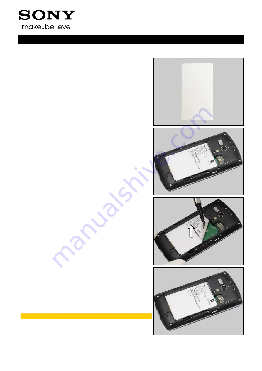
4.10  Core Unit Label 

Follow the 3.1- 3.2 Disassembly instructions! 

Carry out the removal as described below. 
Prepare the new Core Unit Label. 
Carry out the Installation as described below. 

Follow the 5.7 

– 5.8 Reassembly instructions! 


REMOVAL 

 
Copy old Core Unit Label information into the ‘Label Print 
Solution

’ program. 


Peel off the Core Unit Label by using a Flex Film Assembly 
Tool. 


INSTALLATION 
 

Check that the proper label format is loaded in the Zebra 
printer and print a new Label by using the ‘Label Print 
Solution

’ software. 

One label only is allowed! 


Содержание MT25i

Страница 1: ...1262 4094 Rev 3 Sony Mobile Communications AB Company Internal Working Instructions mechanical MT25i Xperia neo L ...

Страница 2: ...Sub SIM PBA Assy 17 4 4 Front Cover Assy 17 4 5 Cushion LCD Shim Black 18 4 6 Display 18 4 7 LCD Frame 18 4 8 Antenna holder 19 4 9 Camera Conductive Adhesive 21 4 10 Core Unit Label 23 4 11 Dome Sheet 25 4 12 Function Key 26 4 13 Gasket LCM Connector 28 4 14 Gasket PBA 29 4 15 Gasket Receiver Connector 30 4 16 Gasket TP Connector 31 4 17 Kapton LCM FPC 32 4 18 LED indicator LED indicator adhesive...

Страница 3: ... Swap 57 4 32 1 Board Swap Replacement 57 4 32 2 Board Swap Change Label 57 4 32 3 Board Swap Customize of Software 57 5 Reassembly 58 5 1 Main PBA LCD Frame 58 5 2 Display 62 5 3 Cushion LCD Shim Black 64 5 4 Front Cover Assy 66 5 5 Sub SIM PBA Assy 68 5 6 Rear Cover Assembly 68 5 7 Battery 70 5 8 Battery Cover 70 6 Revision History 71 For general information about mechanical repair related issue...

Страница 4: ...Working Instruction Repair Instruction Mechanical 1262 4094 Rev 3 Sony Mobile Communications AB Company Internal 4 71 1 Exterior Views 1 1 MT25i ...

Страница 5: ...Mobile Communications AB Company Internal 5 71 2 Tools SPECIAL TOOLS 1 Guitar Pick 2 Flex Film Assembly Tool 3 Front Opening Tool 4 Torque Screwdriver 5 Bits JCIS No 0 6 Bits T5 For part no s on the tools above refer to the Tools Catalogue Matrix STANDARD TOOLS 1 Tweezers ...

Страница 6: ...one in the following order 1 Battery Cover 2 Battery 3 Rear Cover Assembly 4 Sub SIM PBA Assy 5 Front Cover Assy 6 Cushion LCD Shim Black 7 Display 8 Main PBA a LCD Frame b 3 1 Battery Cover Release the Battery Cover from the cavity at bottom side by fingers Lift up the Battery Cover and remove it 3 2 Battery Use finger to release the Battery as shown ...

Страница 7: ...Company Internal 7 71 Disassembly Lift to remove the Battery 3 3 Rear Cover Assembly Remove the four Screw_M1 6X4 2 by using a screwdriver with Bits T5 Remove the six Screw_M1 4X2 8 by using a screwdriver with Bits JCIS No 0 Remove the two Screw_M1 4X2 4 by using a screwdriver with Bits JCIS No 0 ...

Страница 8: ... the Spring Pins under the Rear Cover as shown in the picture Slide it along to release the bottom side Insert a Guitar Pick and slide along to release the left side Do not touch the Spring Pins under the Rear Cover as shown in the picture Lift up the Rear Cover Assembly and push to release the hooks at the top side gently as shown Note the Audio Jack in the middle of the top side as shown in the ...

Страница 9: ...ernal 9 71 Disassembly Separate the Rear Cover Assembly and the Unit 3 4 Sub SIM PBA Assy Insert the Guitar Pick underneath the Sub SIM PBA Assy and pull upwards gently to unsnap the BtB connector Remove the Sub SIM PBA Assy 3 5 Front Cover Assy Detach to remove the Gasket TP Connector Scrap Not to be reused ...

Страница 10: ...cations AB Company Internal 10 71 Disassembly Unlock the ZIF connector by using a Front Opening Tool Release the flex part from the ZIF connector Detach the FPC from up right corner and slide along the edge to release the FPC adhesive There are seven hooks securing the Front Cover Assy ...

Страница 11: ... Internal 11 71 Disassembly Insert the Front Opening Tool to release the three hooks of Front Cover Assy from the left side Release the bottom side of Front Cover Assy as shown Insert the Front Opening Tool to release the Front Cover Assy from top of right side Separate the Front Cover Assy and left Unit ...

Страница 12: ...cations AB Company Internal 12 71 Disassembly 3 6 Cushion LCD Shim Black Turn over the unit there are four hooks securing the Display Unsnap the hooks of Display at the bottom side as the order shown in the picture Do the same for the other two hooks Turn the Display to about 90 degrees ...

Страница 13: ...nd remove the Cushion LCD Shim Black 3 7 Display Detach the Gasket LCM Connector by using a Flex Film Assembly Tool Note Take care of the ZIF connector under the Kapton LCM FPC Scrap Not to be reused Detach the Kapton LCM FPC by using a Flex Film Assembly Tool Note Take care of the ZIF connector under the Kapton LCM FPC Scrap Not to be reused Unlock the ZIF connector by using a Front Opening Tool ...

Страница 14: ...pany Internal 14 71 Disassembly Release the flex part from the ZIF connector Detach to release the adhesive under the FPC Separate the Display 3 8 Main PBA and LCD Frame Detach the Gasket Receiver Connector Note Take care of the ZIF connector under the Gasket Receiver Connector Scrap Not to be reused ...

Страница 15: ...ons AB Company Internal 15 71 Disassembly Unlock the ZIF connector by using a Front Opening Tool Release the flex part from the ZIF connector Turn over the unit and there are three hooks securing the PBA Insert the Front Opening tool from bottom of right side and lift up to unsnap the hook ...

Страница 16: ...n Mechanical 1262 4094 Rev 3 Sony Mobile Communications AB Company Internal 16 71 Disassembly Do the same for the hook on the opposite side Turn the Main PBA to the right side to release the other hook on the left top corner Separate them ...

Страница 17: ...he 4 8 4 19 4 24 4 29 Removal instructions Prepare the new Rear Cover Assembly Follow the 4 8 4 19 4 24 4 29 Installation instructions Follow the 5 6 5 8 Reassembly instructions 4 3 Sub SIM PBA Assy Follow the 3 1 3 4 Disassembly instructions Prepare the new Sub SIM PBA Assy Follow the 5 5 5 8 Reassembly instructions 4 4 Front Cover Assy Follow the 3 1 3 5 Disassembly instructions Follow the 4 12 ...

Страница 18: ...the new Cushion LCD Shim Black Follow the 5 3 5 8 Reassembly instructions 4 6 Display Follow the 3 1 3 7 Disassembly instructions Prepare the new Display Follow the 5 2 5 8 Reassembly instructions 4 7 LCD Frame Follow the 3 1 3 8 Disassembly instructions Follow the 4 22 Removal instructions Prepare the new LCD Frame Follow the 4 9 4 22 4 30 Installation instructions Follow the 5 1 5 8 Reassembly i...

Страница 19: ...he 3 1 3 2 Disassembly instructions Carry out the removal as described below Prepare the new Antenna holder Carry out the Installation as described below Follow the 5 7 5 8 Reassembly instructions REMOVAL Remove the two Screw_M1 6X4 2 by using a screwdriver with Bits T5 Insert Guitar Pick to unsnap the bottom side Insert Guitar Pick to lift up the right side ...

Страница 20: ...ny Mobile Communications AB Company Internal 20 71 Replacement Antenna holder Remove the Antenna holder INSTALLATION Place the Antenna holder in the correct position Press to secure its position Apply 9 0 9 Ncm torque when tightening the two Screw_M1 6X4 2 with Bits T5 ...

Страница 21: ... Removal instructions Carry out the removal as described below Prepare the new Camera Conductive Adhesive Carry out the Installation as described below Follow the 4 20 Installation instructions Follow the 5 5 5 8 Reassembly instructions REMOVAL Detach Camera Conductive Adhesive by using a Flex Film Assembly Tool INSTALLATION Place the new Camera Conductive Adhesive in the correct position Press to...

Страница 22: ...Working Instruction Repair Instruction Mechanical 1262 4094 Rev 3 Sony Mobile Communications AB Company Internal 22 71 Replacement Camera Conductive Adhesive Peel off the protection tape ...

Страница 23: ... Prepare the new Core Unit Label Carry out the Installation as described below Follow the 5 7 5 8 Reassembly instructions REMOVAL Copy old Core Unit Label information into the Label Print Solution program Peel off the Core Unit Label by using a Flex Film Assembly Tool INSTALLATION Check that the proper label format is loaded in the Zebra printer and print a new Label by using the Label Print Solut...

Страница 24: ...Working Instruction Repair Instruction Mechanical 1262 4094 Rev 3 Sony Mobile Communications AB Company Internal 24 71 Replacement Core Unit Label Press along the surface to secure the attachment ...

Страница 25: ...e the new Dome Sheet Carry out the Installation as described below Follow the 5 1 5 8 Reassembly instructions REMOVAL Detach to remove the Dome Sheet by using a Flex Film Assembly Tool Scrap Not to be reused INSTALLATION Place a new Dome Sheet in the correct position Note the guiding hole as shown in the picture Press along the surface to secure the attachment by fingers Make sure the Dome Sheet i...

Страница 26: ...he removal as described below Prepare the new Function Key Carry out the Installation as described below Follow the 5 4 5 8 Reassembly instructions REMOVAL Release the Function Key from the guiding hole by using a Flex Film Assembly Tool and remove it INSTALLATION Place the Function Key in the correct position Note the guiding poles as shown in the picture Press around the hole to fix it into the ...

Страница 27: ...Working Instruction Repair Instruction Mechanical 1262 4094 Rev 3 Sony Mobile Communications AB Company Internal 27 71 Replacement Function Key Press along to secure Function Key into the cavity ...

Страница 28: ...w Gasket LCM Connector Carry out the Installation as described below Follow the 5 3 5 8 Reassembly instructions REMOVAL Detach the Gasket LCM Connector by using a Flex Film Assembly Tool Note Take care of the ZIF connector under the Gasket LCM Connector Scrap Not to be reused INSTALLATION Place a new Gasket LCM Connector in the correct position Press to secure its position and attachment Note The ...

Страница 29: ...assembly instructions Carry out the removal as described below Prepare the new Gasket PBA Carry out the Installation as described below Follow the 5 5 5 8 Reassembly instructions REMOVAL Remove the Gasket PBA by using a Flex Film Assembly Tool Scrap Not to be reused INSTALLATION Place a new Gasket PBA in the correct position Press to secure its position and attachment ...

Страница 30: ...e the new Gasket Receiver Connector Carry out the Installation as described below Follow the 5 2 5 8 Reassembly instructions REMOVAL Detach the Gasket Receiver Connector Note Take care of the ZIF connector under the Gasket Receiver Connector Scrap Not to be reused INSTALLATION Place a new Gasket Receiver Connector in the correct position Press to secure its position and attachment Note The Gasket ...

Страница 31: ... as described below Prepare the new Gasket TP Connector Carry out the Installation as described below Follow the 5 5 5 8 Reassembly instructions REMOVAL Peel off the Gasket TP Connector by using a Flex Film Assembly Tool Scrap Not to be reused INSTALLATION Place a new Gasket TP Connector in the correct position Press to secure its position and attachment Note The Gasket TP Connector should cover t...

Страница 32: ...re the new Kapton LCM FPC Carry out the Installation as described below Follow the 4 13 Installation instructions Follow the 5 3 5 8 Reassembly instructions REMOVAL Detach the Kapton LCM FPC by using a Flex Film Assembly Tool Note Do not damage the ZIF connector under the Kapton LCM FPC Scrap Not to be reused INSTALLATION Place a new Kapton LCM FPC in the correct position Press to secure its posit...

Страница 33: ... the removal as described below Prepare the new LED indicator LED indicator adhesive Carry out the Installation as described below Follow the 5 6 5 8 Reassembly instructions REMOVAL The LED indicator is in the position as shown in the picture Detach to remove the LED indicator from its cavity Peel off the LED indicator adhesive by using a Flex Film Assembly Tool and clean the residue until it is c...

Страница 34: ... Internal 34 71 Replacement LED indicator LED indicator adhesive INSTALLATION Place a new LED indicator adhesive in the correct position Press to secure its position and attachment Peel off the protection tape Place a new LED indicator in the correct position Note the guiding hole as shown in the picture ...

Страница 35: ... 4094 Rev 3 Sony Mobile Communications AB Company Internal 35 71 Replacement LED indicator LED indicator adhesive Insert the LED indicator into the hole Press to secure its position and attachment into the cavity Press to secure its position and attachment ...

Страница 36: ...ns Carry out the removal as described below Prepare the new Loudspeaker Gasket Speaker Carry out the Installation as described below Follow the 5 6 5 8 Reassembly instructions REMOVAL Detach to remove the Loudspeaker Peel off the Gasket Speaker by using a Flex Film Assembly Tool and clean the residue until it is clean Scrap Not to be reused INSTALLATION Place a new Gasket Speaker in the correct po...

Страница 37: ... Company Internal 37 71 Replacement Loudspeaker Gasket Speaker Press to secure its position and attachment Peel off the protection tape Place a new Loudspeaker in the correct position Note the pin direction as shown in the picture Press to secure its position and attachment Do not touch the pins ...

Страница 38: ...ssembly instructions Follow the 4 9 Removal instructions Carry out the removal as described below Prepare the new Main Camera Carry out the Installation as described below Follow the 4 9 Installation instructions Follow the 5 5 5 8 Reassembly instructions REMOVAL Unsnap the BtB connector Remove the Main Camera INSTALLATION Place a new Main Camera in the correct position ...

Страница 39: ...air Instruction Mechanical 1262 4094 Rev 3 Sony Mobile Communications AB Company Internal 39 71 Replacement Main Camera Press to secure its position and attachment Do not touch the camera lens Press to snap the BtB connector ...

Страница 40: ...y out the removal as described below Prepare the new Mesh Speaker Carry out the Installation as described below Follow the 5 7 5 8 Reassembly instructions REMOVAL Peel off the Mesh Speaker by using a Flex Film Assembly Tool and clean the residue until it is clean Scrap Not to be reused INSTALLATION Place a new Mesh Speaker in the correct position Press around to secure its position and attachment ...

Страница 41: ...Disassembly instructions Carry out the removal as described below Prepare the new PBA Receiver Flex Mylar Tape Receiver Receiver Adhesive Carry out the Installation as described below Follow the 5 1 5 8 Reassembly instructions REMOVAL Detach to release the adhesive under FPC Push from opposite side through the hole to release the adhesive of PBA Receiver Flex Detach to release the adhesive under r...

Страница 42: ...ement PBA Receiver Flex Mylar Tape Receiver Receiver Adhesive Separate the PBA Receiver Flex Detach to remove the Receiver Adhesive and clean the residue until its clean Scrap Not to be reused INSTALLATION Place a new Mylar Tape Receiver in the correct position Note the guiding hole Press to secure its position and attachment ...

Страница 43: ...ernal 43 71 Replacement PBA Receiver Flex Mylar Tape Receiver Receiver Adhesive Place a new Receiver Adhesive in the correct position Press to secure its attachment Peel off the protection tape Place the PBA Receiver Flex in the correct position Note The FPC should be placed at the back side of the LCD Frame ...

Страница 44: ...ns AB Company Internal 44 71 Replacement PBA Receiver Flex Mylar Tape Receiver Receiver Adhesive Press to fix the holes it into the guiding poles Press along the surface to secure its attachment Only the edge of Receiver gasket can be pressed Press the surface of FPC to secure its attachment ...

Страница 45: ...mbly instructions Carry out the removal as described below Prepare the new Receiver Mesh Carry out the Installation as described below Follow the 5 4 5 8 Reassembly instructions REMOVAL Peel off the Receiver Mesh by using a Flex Film Assembly Tool Scrap Not to be reused INSTALLATION Place a new Receiver Mesh in the correct position Press to secure its position and attachment ...

Страница 46: ...bly instructions Carry out the removal as described below Prepare the new Rubber Microphone Carry out the Installation as described below Follow the 5 6 5 8 Reassembly instructions REMOVAL The Rubber Microphone is in the position as shown in the picture Push the Rubber Microphone from the opposite side to remove it INSTALLATION Place a new Rubber Microphone in the correct position ...

Страница 47: ...ompany Internal 47 71 Replacement Rubber Microphone Place the Rubber Microphone into the cavity as shown in the picture and press to secure its position Press to secure its position into the cavity Press to insert it into the cavity The Rubber Microphone should be assembled as shown in the picture ...

Страница 48: ...l as described below Prepare the new Shield can BB Carry out the Installation as described below Follow the 5 1 5 8 Reassembly instructions REMOVAL Unsnap the corners of the Shield can BB by using a pair of Tweezers and pull upwards to remove it Scrap Not to be reused INSTALLATION Place a new Shield can BB in the correct position Press all the corners to snap it Only the edge of the Shield Can is ...

Страница 49: ...l as described below Prepare the new Shield can PA Carry out the Installation as described below Follow the 5 1 5 8 Reassembly instructions REMOVAL Unsnap the corners of the Shield can PA by using a pair of Tweezers and pull upwards to remove it Scrap Not to be reused INSTALLATION Place a new Shield can PA in the correct position Press all the corners to snap it Only the edge of the Shield Can is ...

Страница 50: ...l as described below Prepare the new Shield can RF Carry out the Installation as described below Follow the 5 1 5 8 Reassembly instructions REMOVAL Unsnap the corners of the Shield can RF by using a pair of Tweezers and pull upwards to remove it Scrap Not to be reused INSTALLATION Place a new Shield can RF in the correct position Press all the corners to snap it Only the edge of the Shield Can is ...

Страница 51: ...embly instructions Carry out the removal as described below Prepare the new Side Key Carry out the Installation as described below Follow the 5 7 5 8 Reassembly instructions REMOVAL Detach to remove it Scrap Not to be reused INSTALLATION Place a new Side Key in the correct position Note the guiding hole as shown in the picture Press to secure its position and attachment ...

Страница 52: ...F Hole Follow the 3 1 3 2 Disassembly instructions Carry out the removal as described below Prepare the new Tape RF Hole Carry out the Installation as described below Follow the 5 7 5 8 Reassembly instructions REMOVAL Detach to remove it INSTALLATION Place a new Tape RF Hole in the correct position Press to secure its position and attachment ...

Страница 53: ...the 3 1 3 8 Disassembly instructions Carry out the removal as described below Prepare the new Touch Panel Conductive Adhesive Carry out the Installation as described below Follow the 5 1 5 8 Reassembly instructions REMOVAL Detach to remove it Scrap Not to be reused INSTALLATION Place a new Touch Panel Conductive Adhesive in the correct position Press to secure its attachment ...

Страница 54: ...Working Instruction Repair Instruction Mechanical 1262 4094 Rev 3 Sony Mobile Communications AB Company Internal 54 71 Replacement Touch Panel Conductive Adhesive Peel off the protection tape ...

Страница 55: ...out the removal as described below Prepare the new Water Indicator Carry out the Installation as described below Follow the 5 6 5 8 Reassembly instructions REMOVAL There are two Water Indicators on the phone as shown in the picture Note Replacement method is the same for the two Water Indicators Detach to remove it Scrap Not to be reused INSTALLATION Place a new Water Indicator in the correct posi...

Страница 56: ...Working Instruction Repair Instruction Mechanical 1262 4094 Rev 3 Sony Mobile Communications AB Company Internal 56 71 Replacement Water Indicator Press to secure its position and attachment ...

Страница 57: ...p Board Reuse the Main Camera Follow the 4 20 Installation instructions Follow the 5 1 5 8 Reassembly instructions NOTE Startup the unit to initialize settings before perform Customize Phone in Emma 4 32 2 Board Swap Change Label CHANGE LABEL Follow the instructions in the Generic Repair Manual Build swap for change of label 4 32 3 Board Swap Customize of Software CUSTOMIZE OF SOFTWARE Follow the ...

Страница 58: ...in the following order 1 Main PBA a LCD Frame b 2 Display 3 Cushion LCD Shim Black 4 Front Cover Assy 5 Sub SIM PBA Assy 6 Rear Cover Assembly 7 Battery Cover 8 Battery 5 1 Main PBA LCD Frame Prepare the LCD Frame Peel off the Camera Conductive Adhesive and clean the residue until it is clean Place a new Camera Conductive Adhesive in the correct position ...

Страница 59: ... Communications AB Company Internal 59 71 Reassembly Press to secure its position and attachment Peel off the protection tape Peel off the Touch Panel Conductive Adhesive and clean the residue until it is clean Place a new Touch Panel Conductive Adhesive in the correct position ...

Страница 60: ...Rev 3 Sony Mobile Communications AB Company Internal 60 71 Reassembly Press to secure its position and attachment Peel off the protection tape Prepare the Main PBA and LCD Frame Insert the Main PBA from the left side to hook the Main PBA as shown in the picture ...

Страница 61: ...tion Mechanical 1262 4094 Rev 3 Sony Mobile Communications AB Company Internal 61 71 Reassembly Press to snap the Main PBA Press the Main Camera to secure its position Do not touch the camera lens Turn it over Connect the ZIF connector ...

Страница 62: ...y Mobile Communications AB Company Internal 62 71 Reassembly Lock the ZIF connector Place a new Gasket Receiver Connector in the correct position Press to secure its attachment Note The Gasket Receiver Connector should cover ZIF connector 5 2 Display Prepare the Display ...

Страница 63: ...4 Rev 3 Sony Mobile Communications AB Company Internal 63 71 Reassembly Connect the ZIF connector Do not hold the FPC with adhesive as shown in the picture Lock the ZIF connector Press to secure its attachment Place a new Kapton LCM FPC in the correct position ...

Страница 64: ...ure its position and attachment Note The Kapton LCM FPC should cover the whole ZIF connector Place a new Gasket LCM Connector in the correct position Press to secure its attachment Note The Gasket LCM Connector should cover ZIF connector 5 3 Cushion LCD Shim Black Prepare the Cushion LCD Shim Black Note the direction of Cushion LCD Shim Black ...

Страница 65: ...ev 3 Sony Mobile Communications AB Company Internal 65 71 Reassembly Put it on the LCD Frame Press along the surface to secure the position and attachment Turn over the Display carefully Do not touch the screen Press to secure its position Do not touch the screen ...

Страница 66: ... Internal 66 71 Reassembly 5 4 Front Cover Assy Prepare Front Cover Assy Insert the LCD Frame into the Front Cover Assy from the FPC at the right top corner and lay down the LCD Frame Make sure the FPC is above the LCD Frame Press the FPC to secure its position and attachment Press to secure its position ...

Страница 67: ...obile Communications AB Company Internal 67 71 Reassembly Connect the ZIF connector Lock the ZIF connector Place a new Gasket TP Connector along the edge of Main PBA as shown in the picture Note The Gasket TP Connector should cover ZIF connector Press to secure its position ...

Страница 68: ...5 5 Sub SIM PBA Assy Place the Sub SIM PBA Assy in the correct position Note the guiding pole Press to connect the ZIF connector Make sure the two guiding holes are in correct position Note the Spring as shown in the picture AA 5 6 Rear Cover Assembly Prepare the Rear Cover Assembly Place the Rear Cover Assembly from the top side ...

Страница 69: ...AB Company Internal 69 71 Reassembly Press to secure the seven hooks Apply 9 0 9 Ncm torque when tightening the Screw_M1 4X2 4 with Bits JCIS No 0 Apply 9 0 9 Ncm torque when tightening the Screw_M1 4X2 8 with Bits JCIS No 0 Apply 9 0 9 Ncm torque when tightening the Screw_M1 6X4 2 with Bits T5 ...

Страница 70: ...anical 1262 4094 Rev 3 Sony Mobile Communications AB Company Internal 70 71 Reassembly 5 7 Battery Place the Battery into the cavity Press to secure its position 5 8 Battery Cover Place the Battery Cover from the top Press to secure its position ...

Страница 71: ...n Mechanical 1262 4094 Rev 3 Sony Mobile Communications AB Company Internal 71 71 6 Revision History Rev Date Changes Comments 1 2012 Jun 25 Initial release 2 2012 Jul 27 Update the chapter 4 31 1 3 2012 Sep 10 Add new part Kapton LCM FPC ...

Страница 72: ...1262 4098 Rev 1 Sony Mobile Communications AB Company Internal Test Instructions mechanical MT25i Xperia neo L ...

Страница 73: ...rator 10 2 2 11 Camera 10 2 2 12 Secondary Camera 10 2 2 13 Flash LED 11 2 2 14 Bluetooth 11 2 2 15 WLAN 12 2 2 16 GPS 12 2 2 17 Compass 13 2 2 18 Accelerometer 13 2 2 19 Ambient Light Sensor 14 2 2 20 Proximity switch 14 2 2 21 Pressure Sensor 14 2 2 22 Real time clock 15 2 2 23 Total call time 15 2 2 24 External Memory 15 2 2 25 Security 16 2 2 26 FM Radio 16 2 2 27 Battery test 16 2 2 28 Flip s...

Страница 74: ...ny Internal 3 22 2 4 Network Test 21 2 4 1 On the air call to mobile no UMTS network available 21 2 4 2 On the air call to mobile UMTS network available 21 3 Revision History 22 For general information about test procedures refer to 1220 1333 Generic Repair Manual mechanical ...

Страница 75: ... Water indicator inspection Before starting any tests the liquid intrusion indicator has to be checked The water indicator is located as shown in this picture after the Battery Cover is removed If affected red color handle the phone according to the local directives If not affected by liquid proceed to the Pre Test Preparation below ...

Страница 76: ...20 1333 Generic Repair Manual mechanical 1 2 1 2 Software version update Mandatory first repair action Use the USB cable to connect with the Micro USB connector of the phone for this purpose Ensure the phone is powered off and proceed as follows Open the Emma application and log in Press and hold the volume down key on the phone connect the phone to the USB cable and then release the volume down k...

Страница 77: ...ypad combination 7378423 SONY XPERIA 1 2 3 4 5 6 7 8 9 0 Select Service tests Select one of the tests and follow the test instructions as described below To stop the test and return to the Service tests menu press the Back key For more information refer to 1220 1333 Generic Repair Manual mechanical XPERIA SONY XPERIA Customization Settings Service settings Service info Service tests Service The fo...

Страница 78: ...e Up 2 2 2 Touch Screen Move a finger across the touch screen a line will be drawn as it touches Press the Back key to return to the Service Test Menu SONY XPERIA Touch Screen 2 2 3 Display Minor variations in the display s brightness and color may occur between phones There may be tiny bright dots on the display called defective pixels and which occur when individual dots have malfunctioned and c...

Страница 79: ...nation 2 2 5 Speaker Do not hold the phone close to an ear during this test Make sure that the sound from the speaker port on the left top back side of the phone is emitted loud and clear and that the test includes maximum volume Press the volume up volume down key to adjust the speaker volume Press the Back key to return to the Service Test Menu XPERIA Speaker SONY XPERIA Speaker Speaker 2 2 6 St...

Страница 80: ...evious Speaker test must have been successfully carried out before doing this test The phone will start to record and after approximately ten seconds the sound is played back through the Speaker Speak into the microphone during the Microphone Recording phase Check the quality by listening to the recording from the Speaker during the Playing recorded sound phase at maximum volume Press the Back key...

Страница 81: ...tive camera module Aim the camera located at the back of the phone at an object and check the quality of the image shown in the display Press the screen to preview the photo s auto focus quality Photos are taken but not saved during this test Press the Back key to return to the Service Test Menu 2 2 12 Secondary Camera Minor variations in image appearance may occur between phones but is not uncomm...

Страница 82: ...sequences Step 1 Enable Bluetooth wait 4 5 seconds shows OK Step 2 Searching Step 3 Press Yes to setup its visibility to target SONY XPERIA An application on your phone is requesting permission to turn on Bluetooth and to make your phone discoverable by other devices for 300 seconds Do you want to do this Yes No Bluetooth permission request i Bluetooth Enable Bluetooth OK Searching Device found St...

Страница 83: ...lowing sequences Step 1 Enable WLAN wait 4 5 seconds shows OK Step 2 Searching Step 3 Access points found list Step 4 Select the Target WLAN network and type the password to get connected Step 5 Enter a web address e g Google com Step 6 When connection succeeded it shows Test Complete Press the Back key to return to the Service Test Menu WLAN SONY XPERIA Enable WLAN OK Searching Access points foun...

Страница 84: ...procedures 2 2 18 Accelerometer The accelerometer test displays the actual position of the phone as a 3D coordinate X Y Z Press the Back key to return to the Service Test Menu XPERIA SONY XPERIA Accelerometer X 0 1234 Y 6 7890 Z 0 1234 By tilting the phone in various directions the X Y Z values will change in size and polarity depending on the angle and direction as shown in the adjacent picture C...

Страница 85: ...itch The previous Speaker test should have been successfully carried out before doing this test Make sure the phone is not in silent mode before performing this test When entering into the test the screen shows Proximity switch OFF and a tone is emitted Once your finger cover the proximity switch area on the left side of the receiver the screen will show Proximity switch ON with a different type o...

Страница 86: ...to the Service Test Menu SONY XPERIA Real time clock OK 2 2 23 Total call time The total call time is displayed in the format HH MM SS hours minutes seconds Press the Back key to return to the Service Test Menu SONY XPERIA Total call time 00 01 07 2 2 24 External Memory A memory card should be inserted in the phone before starting this test The phone should detect that the memory card is inserted ...

Страница 87: ...DRM keys are shown in the display There may be different content shown based on different market software versions Press the Back key to return to the Service Test Menu 2 2 26 FM Radio Not applicable do not use Press Back key to return to Service Test Menu 2 2 27 Battery test Do not use Press Back key to return to Service Test Menu ...

Страница 88: ... Tests 2 2 28 Flip slider counter Not applicable do not use Press the Back key to return to the Service Test Menu 2 2 29 Verify certificates Not applicable do not use Press the Back key to return to the Service Test Menu 2 2 30 IrDA Test Not applicable do not use This test is not available for this product ...

Страница 89: ...ress the Back key to return to the Service Test Menu 2 2 32 Connector Ground Test Not applicable do not use Press Back key to return to Service Test Menu 2 2 33 Touch pad test Touch pad test using fingers the display will show white box on screen when fingers touch display Maximum support 4 point touch Press the Back key to return to the Service Test Menu ...

Страница 90: ... card operator name will be displayed above the Time clock when phone is in Lock status If not detected the message Emergency call only will be displayed instead in the pull down Status Bar Press Back key to return to Standby Menu SONY XPERIA Notifications Operator name 2 3 2 On Off key test Press the On Off key for a long time to turn the phone on or off When the phone stands by press the On Off ...

Страница 91: ...tery via a USB port Ensure that no computer application such as PC Suite or Emma is active Do not Connect a USB cable from a computer or charger to the system connector start the phone Verify that the phone is being charged by Notification LED and Battery icon Remove the USB cable from the connector and verify that the notification LED and Battery icon no longer indicates charging SONY XPERIA ...

Страница 92: ...klight illuminates 4 Answer the call and check the sound quality in both phones 5 Adjust the volume up and down with the side keys and verify that the sound level is altered 6 End the call and check that the elapsed time is displayed and that the termination is done properly 2 4 2 On the air call to mobile UMTS network available GSM Go to the phone menu and set Press Menu key Settings Wireless net...

Страница 93: ...Test Instructions mech 1262 4098 Rev 1 Sony Mobile Communications AB Company Internal 22 22 3 Revision History Rev Date Changes Comments 1 2012 Jun 25 Initial release ...

Страница 94: ...1262 4100 Rev 2 Sony Mobile Communications AB Company Internal Troubleshooting Guide mechanical MT25i Xperia neo L ...

Страница 95: ...phone 16 1 8 Microphone 18 1 8 1 Microphone 18 1 9 Vibrator 19 1 9 1 Vibrator not generating alerts 19 1 10 Camera 20 1 10 1 Camera defects 20 1 10 2 Video Call Camera defects 21 1 11 Flash LED 22 1 11 1 Flash LED not flashing 22 1 12 Bluetooth and WLAN 24 1 12 1 Bluetooth or WLAN connection failure 24 1 13 GPS 25 1 13 1 GPS malfunctions 25 1 14 Compass 26 1 14 1 Compass fails 26 1 15 Acceleromete...

Страница 96: ... 22 FM Radio 34 1 22 1 No Poor FM Radio reception 34 1 23 Network Signal 35 1 23 1 No Poor signal 35 1 24 SIM 36 1 24 1 SIM not detected 36 1 24 2 Incorrect SIM indicated 37 1 25 Charging 38 1 25 1 Battery will not charge 38 1 26 HandsFree by Wire 39 1 26 1 Connection to Portable HandsFree fails 39 1 27 Data Communication 40 1 27 1 Data transfer via System Connector fails 40 2 Revision History 41 ...

Страница 97: ...o section 1 4 Display Check Check the contact pads on the battery Action 1 If dirty or oxidized clean the pads 2 If damaged replace the battery Check Check the Battery contact pins Action 1 If dirty or oxidized clean the contact pins 2 If adhesive is detected on the contact pins use an eraser to gently rub off the adhesive 3 If damaged Replace PBA Check Inspect the on off key a and the on off swit...

Страница 98: ...Troubleshooting Guide mech 1262 4100 Rev 2 Sony Mobile Communications AB Company Internal 5 41 Problem Areas Power 2 If the on off key is damaged replace the Side Key 3 Replace PBA ...

Страница 99: ...t the Function Key on the Front Cover Assy Action 1 If the Function Key is dirty or clogged clean it 2 If damaged replace it Check Check the connection between the Dome Sheet on the PBA and the back side of the Function Key Action 1 If dirty or clogged clean them 2 If the Function Key is damaged replace it Check Check the connection between the Dome Sheet and the PBA ...

Страница 100: ...is not properly attached or damaged replace it 2 If the golden pad is dirty clean it 3 Replace PBA 1 2 2 Volume Key Check Inspect the volume key a on the Battery Cover and the volume switches b on the PBA Action 1 If the volume key a or the volume switches b is dirty or clogged clean them 2 If the Side Key is damaged replace it 3 Replace PBA ...

Страница 101: ...Internal 8 41 Problem Areas Keys 1 2 3 On Off key Check Inspect the on off key a on the Front Cover and the on off switch b on the PBA Action 1 If the on off key a or the on off switch b is dirty or clogged clean them 2 If the on off key is damaged replace the Side Key 3 Replace PBA ...

Страница 102: ... the Front Cover Assy and the FPC on the PBA Receiver Flex Action 1 If not properly connected disconnect and reconnect 2 If dirty or oxidized clean it Check Inspect the Front Cover Assy and its FPC Action 1 If the FPC or the touch screen is damaged replace the Front Cover Assy Check Inspect the both sides of the ZIF connector on the PBA and the FPC on the PBA Receiver Flex Action 1 If not properly...

Страница 103: ...ony Mobile Communications AB Company Internal 10 41 Problem Areas Touch Screen Check Inspect the PBA Receiver Flex Action 1 If the PBA Receiver Flex is damaged replace the PBA Receiver Flex Mylar Tape LCD Frame and Receiver Adhesive 2 Replace PBA ...

Страница 104: ...ed Action If the activation described above is not detected refer to section 1 1 Power Check Inspect the both sides of the ZIF connector on the Main PBA and the FPC of the Display Action 1 If not properly connected disconnect and reconnect 2 If dirty or oxidized clean it Check Inspect the Display and its FPC Action 1 If the Display or its FPC is damaged replace the Display Gasket LCM Connector Kap...

Страница 105: ...1 5 1 LED Illumination Check Inspect the external port of the LED Indicator Action 1 If dirty clean it 2 If the external port is damaged replace the Battery Cover Check Inspect the LED Indicator Action 1 If the LED Indicator is dirty clean it 2 If the LED Indicator is damaged replace the LED Indicator and the LED Indicator Adhesive ...

Страница 106: ...roubleshooting Guide mech 1262 4100 Rev 2 Sony Mobile Communications AB Company Internal 13 41 Problem Areas LED Illumination Check Inspect the RGB LED on the PBA Action 1 If dirty clean it 2 Replace PBA ...

Страница 107: ...er Check Inspect the Loudspeaker s external port on the Battery Cover Action If clogged clean the loudspeaker port Check Inspect the Mesh Speaker on the Rear Cover Assembly Action If the Mesh Speaker is damaged replace it Check Check the connection between Loudspeaker contact pins and contact pads on the PBA Action 1 If dirty clean them ...

Страница 108: ...ooting Guide mech 1262 4100 Rev 2 Sony Mobile Communications AB Company Internal 15 41 Problem Areas Speaker 2 If the Loudspeaker or its pins are damaged replace the Loudspeaker and Gasket Speaker 3 Replace PBA ...

Страница 109: ...r s external port on the Front Cover Assy Action If clogged clean it Check Inspect the Receiver Mesh on the Front Cover Assy Action If the Receiver Mesh is damaged replace it Check Inspect the both sides of the ZIF connector on the PBA and the FPC on the PBA Receiver Flex Action 1 If not properly connected disconnect and reconnect 2 If dirty or oxidized clean it ...

Страница 110: ...unications AB Company Internal 17 41 Problem Areas Earphone Check Inspect the PBA Receiver Flex and the Receiver Action 1 If the PBA Receiver Flex or the receiver is damaged replace the PBA Receiver Flex Mylar Tape LCD Frame and Receiver Adhesive 2 Replace PBA ...

Страница 111: ...t the Microphone s external port on the Battery Cover Action If dirty or clogged clean the port Check Inspect the Mesh Microphone on the Battery Cover Action If dirty clean it Check Inspect the Rubber Microphone and the Microphone on the PBA Liquid is not allowed Action 1 If dirty clean them 2 If the Rubber Microphone is damaged replace it 3 Replace PBA ...

Страница 112: ...Troubleshooting Guide mech 1262 4100 Rev 2 Sony Mobile Communications AB Company Internal 19 41 Problem Areas 1 9 Vibrator 1 9 1 Vibrator not generating alerts Action Replace PBA ...

Страница 113: ...Action 1 If dirty clean it 2 If the camera window is scratched or damaged replace the Rear Cover Assembly Check Check the BtB connector of the Camera to the PBA Action 1 If not properly connected disconnect and reconnect 2 If dirty or oxidized clean both sides of the BtB connector Check Inspect the Camera Action 1 If the Camera is damaged replace the Camera and Camera Conductive Adhesive 2 Replace...

Страница 114: ...hed or damaged replace the Front Cover Assy Check Inspect the both sides of the ZIF connector on the PBA and the FPC on the PBA Receiver Flex Action 1 If not properly connected disconnect and reconnect 2 If dirty or oxidized clean it Check Inspect the PBA Receiver Flex and the VGA camera on it Action 1 If dirty clean it 2 If the VGA camera or the PBA Receiver Flex is damaged replace the PBA Receiv...

Страница 115: ...ndow of the flash LED on the Rear Cover Assembly Action 1 If dirty clean the window 2 If scratched or damaged replace the Rear Cover Assembly Check Inspect the Flash LED on the Sub SIM PBA Assy Action If dirty clean it Check Inspect the BtB connector of the Sub SIM PBA Assy to the PBA Action 1 If not properly connected disconnect and reconnect 2 If dirty or oxidized clean it ...

Страница 116: ...ide mech 1262 4100 Rev 2 Sony Mobile Communications AB Company Internal 23 41 Problem Areas Flash LED 3 If the Flash LED or the BtB connector of the Sub SIM PBA Assy is damaged replace the Sub SIM PBA Assy 4 Replace PBA ...

Страница 117: ...heck Inspect the WLAN and Bluetooth antenna on the Rear Cover Assembly Action 1 If dirty clean it 2 If the pads are damaged replace the Rear Cover Check Inspect the WLAN and Bluetooth antenna contact pads on the Rear Cover Assembly and the contact pins on the PBA Action 1 If dirty or oxidized clean the pads and pins 2 If the pads are damaged replace the Rear Cover 3 Replace PBA ...

Страница 118: ...t the GPS antenna on the Rear Cover Assembly Action 1 If dirty clean it 2 If the pads are damaged replace the Rear Cover Assembly Check Inspect the GPS antenna contact pads on the Rear Cover Assembly and the contact pins on the PBA Action 1 If dirty or oxidized clean the pads and pins 2 If the pads are damaged replace the Rear Cover Assembly 3 Replace PBA ...

Страница 119: ...Troubleshooting Guide mech 1262 4100 Rev 2 Sony Mobile Communications AB Company Internal 26 41 Problem Areas 1 14 Compass 1 14 1 Compass fails Action Replace PBA ...

Страница 120: ...Troubleshooting Guide mech 1262 4100 Rev 2 Sony Mobile Communications AB Company Internal 27 41 Problem Areas 1 15 Accelerometer 1 15 1 Accelerometer test fails Action Replace PBA ...

Страница 121: ...on the Front Cover Assy Action If dirty clean it Check Inspect the both sides of the ZIF connector on the PBA and the FPC on the PBA Receiver Flex Action 1 If not properly connected disconnect and reconnect 2 If dirty or oxidized clean it Check Inspect the PBA Receiver Flex Action 1 If the PBA Receiver Flex or its light sensor is damaged replace the PBA Receiver Flex Mylar Tape LCD Frame and Recei...

Страница 122: ...on the Front Cover Assy Action 1 If dirty clean it Check Inspect the both sides of the ZIF connector on the PBA and the FPC on the PBA Receiver Flex Action 1 If not properly connected disconnect and reconnect 2 If dirty or oxidized clean it Check Inspect the PBA Receiver Flex Action 1 If the PBA Receiver Flex its sensor or switch is damaged replace the PBA Receiver Flex Mylar Tape LCD Frame and Re...

Страница 123: ...Troubleshooting Guide mech 1262 4100 Rev 2 Sony Mobile Communications AB Company Internal 30 41 Problem Areas 1 18 Real Time Clock 1 18 1 Real Time Clock test fails Action Replace PBA ...

Страница 124: ...Troubleshooting Guide mech 1262 4100 Rev 2 Sony Mobile Communications AB Company Internal 31 41 Problem Areas 1 19 Total call time 1 19 1 Total call time fails Action Replace PBA ...

Страница 125: ...em Areas 1 20 External Memory 1 20 1 Memory Card not detected Check Inspect the memory card holder and check if a memory card can be properly inserted Action If dirty or clogged clean the holder Check Inspect the memory card holder on the PBA Action 1 If dirty or clogged clean the holder 2 Replace PBA ...

Страница 126: ...Troubleshooting Guide mech 1262 4100 Rev 2 Sony Mobile Communications AB Company Internal 33 41 Problem Areas 1 21 Security 1 21 1 Security fails Action Replace PBA ...

Страница 127: ... Company Internal 34 41 Problem Areas 1 22 FM Radio 1 22 1 No Poor FM Radio reception Check Inspect the Audio Jack Connector Action If dirty or clogged clean the connector Check Inspect the Audio Jack Connector on the PBA Action 1 If dirty or oxidized clean it 2 Replace PBA ...

Страница 128: ...gnal Check Inspect the main antenna on the Rear Cover Assembly Action 1 If dirty clean it 2 If damaged replace the Antenna Holder Check Inspect the main antenna contact pins on the Rear Cover Assembly and contact pads on the PBA Action 1 If dirty or oxidized clean the pads and pins 2 If the pads are damaged replace the Antenna Holder 3 Replace PBA ...

Страница 129: ...ty or oxidized clean the holder Check Inspect the SIM card holder of the Sub SIM PBA Assy Action If dirty or oxidized clean the holder Check Inspect the BtB connector of the Sub SIM PBA Assy to the PBA Action 1 If not properly connected disconnect and reconnect 2 If dirty or oxidized clean it 3 If the SIM holder or the BtB connector of the Sub SIM PBA Assy is damaged replace the Sub SIM PBA Assy 4...

Страница 130: ...nications AB Company Internal 37 41 Problem Areas SIM 1 24 2 Incorrect SIM indicated Check Check whether the phone is locked to a particular operator and whether the correct operator SIM is being used Action 1 Use a proper operator SIM or test SIM 2 Replace PBA ...

Страница 131: ...ct pads of the Battery Action 1 If dirty or oxidized clean the pads 2 If damaged replace the Battery Check Inspect the Battery Contact pins Action 1 If dirty or oxidized clean the contact pins 2 If adhesive is detected on the contact pins use an eraser to gently rub off the adhesive Check Inspect the USB connector Action 1 If dirty or oxidized clean the connector 2 Replace PBA ...

Страница 132: ...ternal 39 41 Problem Areas 1 26 HandsFree by Wire 1 26 1 Connection to Portable HandsFree fails Check Inspect the Audio Jack Connector Action If dirty or clogged clean the connector Check Inspect the Audio Jack Connector on the PBA Action 1 If dirty or oxidized clean it 2 Replace PBA ...

Страница 133: ...ev 2 Sony Mobile Communications AB Company Internal 40 41 Problem Areas 1 27 Data Communication 1 27 1 Data transfer via System Connector fails Check Inspect the USB connector Action 1 If dirty or oxidized clean the connector 2 Replace PBA ...

Страница 134: ...leshooting Guide mech 1262 4100 Rev 2 Sony Mobile Communications AB Company Internal 41 41 2 Revision History Rev Date Changes Comments 1 2012 Jun 25 Initial release 2 2012 Sep 11 Update Chapter 1 4 Display ...

Страница 135: ...1262 4102 Rev 1 Sony Mobile Communications AB Company Internal Repair Movies mechanical Xperia neo L MT25i ...

Страница 136: ...picture quality select Actual size or 100 as zoom level in Acrobat Reader To magnify while keeping an acceptable picture quality increase the zoom level to 200 If the movies appear to be jerky or blurred when viewing on line this is probably caused by the connection speed being too slow In that case right click with the mouse on the document name and select Save Target As to download the repair mo...

Страница 137: ...ly 1 Battery Cover 2 Battery 3 Rear Cover Assembly 4 Sub SIM PBA Assy 5 Front Cover Assy 6 Cushion LCD Shim Black 7 Display 8 Main PBA a LCD Frame b 1 2 Reassembly 1 Main PBA a LCD Frame b 2 Display 3 Cushion LCD Shim Black 4 Front Cover Assy 5 Sub SIM PBA Assy 6 Rear Cover Assembly 7 Battery Cover 8 Battery ...

Страница 138: ...Repair Movies mech 1262 4102 Rev 1 Sony Mobile Communications AB Company Internal 4 4 2 Revision History Rev Date Changes Comments 1 2012 Jun 25 Initial release ...

Страница 139: ...1262 4103 Rev 2 Sony Mobile Communications AB Company Internal Part List mechanical MT25i Xperia neo L ...

Страница 140: ...Part List mech 1262 4103 Rev 2 Sony Mobile Communications AB Company Internal 2 8 CONTENTS 1 Part List 3 2 Revision History 8 ...

Страница 141: ... referred to by a simple descriptive name for better understanding Both names designations will in that case be included in this Part List where the name being used in the documents mentioned above is underlined e g Battery Cover Designation Part No Part Location Antenna holder 80010004002 Battery Cover Battery Cover Black Battery Cover White 196PHO0000A 191PHO0002A Camera Conductive Adhesive 56BP...

Страница 142: ...Part Location Front Cover Assy Front Cover Assy Black Front Cover Assy White 124PHO00000 124PHO00001 Function Key 1261 6272 Gasket LCM Connector 56DPHO00004 Gasket PBA 455PHO0110A Gasket Receiver Connector 56DPHO00006 Gasket Speaker 56EPHO00000 Gasket TP Connector 56DPHO00005 Kapton LCM FPC 56GPHO00001 ...

Страница 143: ...nation Part No Part Location LCD Frame 159PHO0000A LED indicator 468PHO00501 LED indicator adhesive 56BPHO00003 Loudspeaker Loudspeaker 11x15 1001 0324 Main Camera Camera 5 MPixel CMOS AF SOC FL 1231 8040 Mesh Speaker 56APHO00001 Mylar Tape Receiver 464PHO00103 PBA Receiver Flex 1229 2860 ...

Страница 144: ... Internal 6 8 Designation Part No Part Location Rear Cover Assembly 199PHO0000A Receiver Adhesive 56BPHO00004 Receiver Mesh 56APHO00003 Rubber Microphone 455PHO0010A Screw_M1 4X2 4 F50001402410 Screw_M1 4X2 8 1262 1720 Screw_M1 6X4 2 1262 1718 Shield can BB 440PHO0320A ...

Страница 145: ...al 7 8 Designation Part No Part Location Shield can PA 440PHO0520A Shield can RF 440PHO0420A Side Key Side Key Black Side Key White 1261 6271 460PHO00502 Sub SIM PBA Assy 120PHO00000 Tape RF Hole 464PHO00101 Touch Panel Conductive Adhesive 56FPHO00000 Water Indicator 1265 2798 ...

Страница 146: ...Part List mech 1262 4103 Rev 2 Sony Mobile Communications AB Company Internal 8 8 2 Revision History Rev Date Changes Comments 1 2012 Jun 25 Initial release 2 2012 Sep 10 Add new part Kapton LCM FPC ...

Страница 147: ...1262 4107 Rev 1 Sony Mobile Communications AB Company Internal Go No Go Test electrical MT25i ...

Страница 148: ...Mobile Communications AB Company Internal 2 8 CONTENTS 1 Go No Go Testing 3 1 1 Antenna Coupler 3 1 2 Direct Line 4 1 3 Attenuation Factors 6 1 3 1 Loss Values Antenna Coupler 6 1 3 2 Loss Values Direct Line 7 2 Revision History 8 This product is ONLY implemented in SERP II ...

Страница 149: ...atalogue Matrix 1 1 Antenna Coupler The following equipment has to be used Rohde Schwartz RF Shield Package Rohde Schwartz RF Shield Box Rohde Schwartz RF Coupler Grid Positioning Holder RF Test Cable Flexible 1M RF Adapter for RF Shield Box USIM Card instrument specific GSM 850 900 1800 1900 WCDMA 850 900 1900 2100 Put the grid positioning holder with its reference point in position G13 and place...

Страница 150: ...rnal 4 8 Go NoGo Testing 1 2 Direct Line The following equipment has to be used RF Test Cable Flexible 1M RF Probe USIM Card instrument specific Connect the RF Probe as shown in the adjacent picture To get access to the RF connector on the PBA refer to 1262 4094 MT25 Mechanical Working Instructions Chapter 3 1 ...

Страница 151: ...ternal 5 8 Go NoGo Testing Follow the directions stated in Go NoGo Test Script Parameters to be found in 1220 1336 Generic Repair Manual electrical together with the Attenuation Factors below This phone is available as one version MT25i including the following bands MT25i GSM 850 900 1800 1900 WCDMA 900 2100 ...

Страница 152: ...ges is being used 1 3 1 Loss Values Antenna Coupler Attenuation MT25i Band Channel Rx Tx GSM 850 Low 7 50 8 89 Mid 7 00 7 99 High 5 00 5 55 GSM 900 Low 8 00 6 92 Mid 8 00 7 06 High 6 00 4 75 GSM 1800 Low 19 00 16 91 Mid 16 00 13 59 High 15 50 14 69 GSM 1900 Low 13 50 17 19 Mid 13 00 15 56 High 13 00 14 46 WCDMA 850 Low Mid High WCDMA 900 Low 6 00 5 77 Mid 6 50 5 96 High 5 50 6 44 WCDMA 1900 Low Mi...

Страница 153: ...s AB Company Internal 7 8 Go NoGo Testing Attenuation Factors 1 3 2 Loss Values Direct Line Attenuation Band Channel Rx Tx GSM 850 All 1 0 1 0 GSM 900 All 1 0 1 0 GSM 1800 All 2 3 2 3 GSM 1900 All 2 3 2 3 WCDMA 850 All 2 5 2 5 WCDMA 900 All 2 5 2 5 WCDMA 1900 All 1 3 1 3 WCDMA 2100 All 1 3 1 3 ...

Страница 154: ...Test and Calibration Repair Instruction Electrical 1262 4107 Rev 1 Sony Mobile Communications AB Company Internal 8 8 2 Revision History Rev Date Changes Comments 1 2012 June 19 Initial release ...

Страница 155: ...1262 4125 Rev 2 Sony Ericsson Mobile Communications AB Company Internal Customization build swap Xperia neo L MT25i ...

Страница 156: ... CONTENTS 1 Emma Login Script Execution 3 2 Customization Workflow 4 2 1 Customize Unit 5 2 1 1 Customization 5 2 2 Customize to Ship or Build Swap 6 2 2 1 Customize to Ship 6 2 2 2 Build Swap 6 3 Revision History 7 For general information about Customization and Swap refer to 1221 5655 Generic Repair Manual build swap ...

Страница 157: ...but do not connect the cable to the phone The USB Activation Dongle has to be inserted into one of the computer s USB ports to be able to log in To execute a Customization or Activation you need to be properly logged on to the Emma application by using your User ID and Password To execute a Customization Script or Activation Script or any other function check that the phone is powered off press an...

Страница 158: ...Customization Repair Instruction Build Swap 1262 4125 Rev 2 Sony Ericsson Mobile Communications AB Company Internal 4 7 2 Customization Workflow Not required for Quick Customization ...

Страница 159: ...CDF CDFId if that script is not available locally select Server search for a complete list of available scripts When creating a build swap unit select an Exchange Unit as the customization scripts choose the desired script the application will download all necessary software to run the script and then flash that software to the phone after successful update disconnect the phone from the USB Cable ...

Страница 160: ...l on the Exchange Unit Box LabelMake instructions to be found on CSPN under LabelMake 2 2 1 2 Customize Mechanics If necessary apply the proper custom mechanical parts co branding keyboard etc for the variant being created in accordance with the Cross Reference List by following the instructions of 1262 4094 Working Instructions mechanical 2 2 2 Build Swap 2 2 2 1 Label Unit Using a red marker lab...

Страница 161: ...n Repair Instruction Build Swap 1262 4125 Rev 2 Sony Ericsson Mobile Communications AB Company Internal 7 7 3 Revision History Rev Date Changes Comments 1 2012 06 23 Initial release 2 2012 08 10 Update the template ...

Отзывы: