4
MEX-R5
MODEL IDENTIFICATION
Label indication
Signal format
Region
Part No.
Destination
system
code
NTSC
1
2-631-964-01 US, Canadian models
PAL
2
2-631-969-01 AEP, UK models
PAL
5
2-638-206-01 Russian model
PAL
3
2-634-525-01 E: PAL model
NTSC
4
2-634-528-01 E: NTSC model
PAL
6
2-639-072-01 Chinese model
SECTION 1
SERVICING NOTES
The laser diode in the optical pick-up block may suffer electrostatic
break-down because of the potential difference generated by the
charged electrostatic load, etc. on clothing and the human body.
During repair, pay attention to electrostatic break-down and also
use the procedure in the printed matter which is included in the
repair parts.
The flexible board is easily damaged and should be handled with
care.
NOTES ON LASER DIODE EMISSION CHECK
Never look into the laser diode emission from right above when
checking it for adjustment. It is feared that you will lose your sight.
NOTES ON HANDLING THE OPTICAL PICK-UP
BLOCK OR BASE UNIT
UNLEADED SOLDER
Boards requiring use of unleaded solder are printed with the lead-
free mark (LF) indicating the solder contains no lead.
(Caution: Some printed circuit boards may not come printed with
the lead free mark due to their particular size)
: LEAD FREE MARK
Unleaded solder has the following characteristics.
•
Unleaded solder melts at a temperature about 40 ˚C higher
than ordinary solder.
Ordinary soldering irons can be used but the iron tip has to be
applied to the solder joint for a slightly longer time.
Soldering irons using a temperature regulator should be set to
about 350 ˚C.
Caution: The printed pattern (copper foil) may peel away if
the heated tip is applied for too long, so be careful!
•
Strong viscosity
Unleaded solder is more viscou-s (sticky, less prone to flow)
than ordinary solder so use caution not to let solder bridges
occur such as on IC pins, etc.
•
Usable with ordinary solder
It is best to use only unleaded solder but unleaded solder may
also be added to ordinary solder.
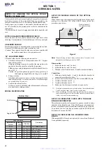
NOTE FOR FLEXIBLE BOARD OF THE OPTICAL
PICK-UP
When connecting or disconnecting the flexible board of the optical
pick-up to or from the CN2 of the SERVO board, follow the
procedure given below.
Figure 1
Note:
When soldering the short lands, solder within 5 seconds at the
temperature of soldering iron below 300
°
C.
Disconnection:
1. Solder the lands 3 and 2 to short.
2. Solder the lands 1 and 2 to short.
3. Disconnect the flexible board. (Unsolder the shorted lands)
Connection:
1. Make sure that the lands 1, 2, and 3 of the flexible board to be
connected are soldered to short.
(*1)
2. Connect the flexible board to the CN2 of the SERVO board.
3. Unsolder the lands 1 and 2.
(*2)
4. Unsolder the lands 3 and 2.
(*2)
5. Make sure that the respective lands are open surely.
*1)
If the lands concerned are not soldered to short, first solder the lands
3 and 2, and then lands 1 and 2 to short in this order.
*2)
When unsoldering the lands, move the soldering iron in bottom to
top direction in Figure 1 so that the solder runs away into the land 4
(solder reservoir) for easy unsoldering.
NOTE FOR OPERATION CHECK WITH THE BASE
BOARD DISCONNECTED
This set detects whether the front panel is opened or closed by using
the S961 of the BASE board. If the BASE board is disconnected,
the S961 is turned off (panel closed status) and the disc is not ejected.
To perform the disc ejecting operation with the BASE board
disconnected, turn on the S961.
NOTE FOR REPLACING THE MOUNTED MAIN
BOARD
If the mounted MAIN board was replaced, be sure refer to Technical
News published separately.
– Bottom View –
4
2
1
Flexible board of
the optical pick-up
SERVO board CN2
3
www. xiaoyu163. com
QQ 376315150
9
9
2
8
9
4
2
9
8
TEL 13942296513
9
9
2
8
9
4
2
9
8
0
5
1
5
1
3
6
7
3
Q
Q
TEL 13942296513 QQ 376315150 892498299
TEL 13942296513 QQ 376315150 892498299


