9
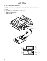
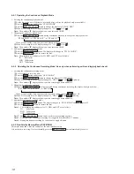
Back up board
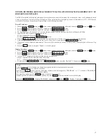
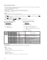
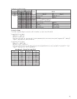
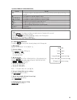
FLUORESCENT DISPLAY TUBE ALL LIGHTING AND KEY CHECK MODE
In this mode, the fluorescent display tube check and key check can be performed.
Procedure:
1. While pressing the INPUT button and
r
(REC) button, insert the power plug into the outlet.”
2. The fluorescent display tube displays “FL ALL 10n Key” momentarily and lights up completely.”
3. The display goes off partially each time a button is pressed.
4. When all buttons are pressed, “Push INPUT” is displayed.
5. When the INPUT button is pressed, the fluorescent display tube displays “Seg Chk” momentarily and lights up partially.
6. When the INPUT button is pressed, it displays “Rmk Chk” momentarily followed by “Push Rmc Key”.
If not using a remote commander, end there and disconnect the power plug from the outlet. If using a remote commander, press any
button.”
7. The check is completed when “Chk End!”is displayed. Press the I/
u
button to end.”
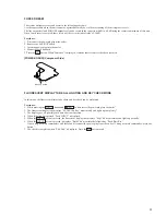
FORCED RESET
The system microprocessor can be reset in the following procedure.
Use these procedure when the unit cannot be operated normally due to the overrunning of the microprocessor, etc.
The line output level and PHONES output level can be varied in the range from 0 dB to -40 dB using the remote commander of this unit.
When forced reset is executed, these levels will be set to the initial value of -20 dB.
Procedure :
1. Disconnect the power plug from the outlet.
2. Remove the BACK UP board.
3. Insert the power plug into the outlet.
4. Mount the back up board.
5. Press the I/
u
button. When “Initialize” is displayed, it means that forced reset has been executed.
[POWER BOARD] (Component Side)


