background image

MDR-RF845R

AEP Model

UK Model

SERVICE MANUAL

HEADPHONES

Sony Corporation

Personal Audio Company

Published by Sony Engineering Corporation

9-927-958-12

2001K1600-1

© 2001.11

Ver 1.2  2001. 11

Headphones

MDR-RF845R

Transmitter

TMR-RF845R

MDR-RF845R is the component model block one in the MDR-RF845RK.

COMPONENT MODEL NAME FOR MDR-RF845RK

SPECIFICATIONS

Headphones

Power source

DC 2.4 V: Built-in rechargeable

battery

Mass

Approx. 240 g (8.1 oz.) incl.
built-in rechargeable battery

Built-in Ni-Cd rechargeable battery

Model name

NC-AA

Voltage

1.2 V

Capacity

700 mAh

Design and specifications are subject to change without

notice.

Содержание MDR-RF845R

Страница 1: ...R Transmitter TMR RF845R MDR RF845R is the component model block one in the MDR RF845RK COMPONENT MODEL NAME FOR MDR RF845RK SPECIFICATIONS Headphones Power source DC 2 4 V Built in rechargeable battery Mass Approx 240 g 8 1 oz incl built in rechargeable battery Built in Ni Cd rechargeable battery Model name NC AA Voltage 1 2 V Capacity 700 mAh Design and specifications are subject to change witho...

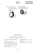
Страница 2: ...heck the interboard wiring to ensure that no wires are pinched or contact high wattage resistors 3 Look for unauthorized replacement parts particularly transistors that were installed during a previous repair Point them out to the customer and recommend their replacement 4 Look for parts which through functioning show obvious signs of deterioration Point them out to the customer and recommend thei...

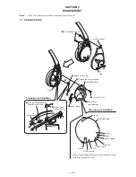
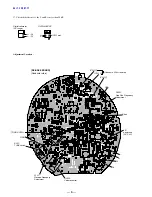
Страница 3: ...talltion Precaution for installtion 7 RX BASE board q Switch push 1 key Cover R hanger No 203 No 203 black No 202 red No 201 green No 201 No 204 No 205 No 204 No 202 4 Screw P 2 8 1 Five screws P 2 6 2 Set the psuh switch 1 key Suspender 1 Slide the suspender in the direction of the arrow 6 Button tuning Claw Claw 2 5 8 2 1 RX BASE BOARD Note Follow the disassembly procedure in the numerical order...

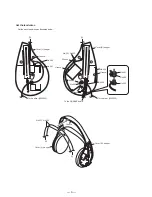
Страница 4: ...01 No 203 Groove Set the lead wires No 204 No 205 No 202 No 202 No 203 No 201 Set the each lead wires as illustrated below Cover R hanger A B Cover R hanger Groove Groove Groove Groove Groove To the driver 030F032 To the RX BASE board Groove To the driver 030F032 B A ...

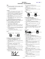
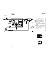
Страница 5: ...transmitter off check the waveform of the oscilloscope as follows 12 Set the transmitter CHANNEL switch to 1 13 Push the headphones tuning switch S301 to receive radio frequency 14 Check same step 8 15 Set the transmitter CHANNEL switch to 3 16 Push the headphones tuning switch S301 to receive radio frequency 17 Check same step 8 3 3 Carrier Modulation Check 1 Set the transmitter CHANNEL switch to...

Страница 6: ...ILLOSCPE L CH1 CH2 17 Check the difference of the L and R to more than 20 dB Ver 1 2 2001 11 IC301 7 IC301 4 IC301 6 GND Short L L R R GND TP R312 C320 Connect a 33k Ω resistor RV301 Free Run Frequency Adjustment B power line DC 2 4V RV302 Volume control L301 Receive Frequency Adjustment S301 TUNE switch ...

Страница 7: ...µF unless otherwise noted pF µµF 50 WV or less are not indicated except for electrolytics and tantalums All resistors are in Ω and 1 4 W or less unless otherwise specified internal component A B Line H adjustment for repair Power voltage is dc 2 4 V and fed with regulated dc power supply from battery terminal Voltages are dc with respect to ground under no signal conditions Voltages are taken with...

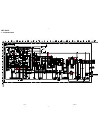
Страница 8: ...MDR RF845R 4 2 SCHEMATIC DIAGRAM 9 10 ...

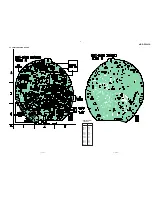
Страница 9: ...MDR RF845R 4 3 PRINTED WIRING BOARD 11 12 Ref No Location D301 B 1 D303 B 3 D304 B 2 D310 C 2 IC301 A 2 IC302 C 2 IC303 A 1 IC304 B 3 IC305 B 2 Q301 B 3 Q303 B 2 Q304 B 2 Q305 B 2 Semiconductor Location ...

Страница 10: ...MDR RF845R MEMO ...

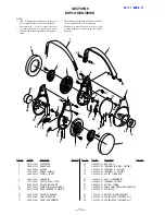
Страница 11: ...ENDER 2 3 046 671 01 BAND HEAD 3 3 046 692 01 PAT EAR 4 1 542 400 11 DRIVER 030F032 5 3 046 685 01 PLATE L FRONT 6 3 046 675 01 HANGER R 7 1 771 249 11 SWITCH PUSH 1 KEY 8 4 992 281 01 HOLDER BALL SHAFT 9 4 981 975 01 SPRING FREE ADJUSTMENT 10 A 4542 649 A RX BASE BOARD COMPLETE 11 3 046 677 01 COVER R HANGER 12 3 049 799 01 LIGHT MDR GUIDE 13 3 046 679 01 CAP R ORNAMENTAL 14 3 046 674 01 HANGER L...

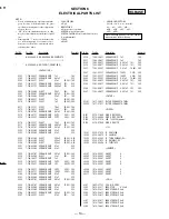
Страница 12: ...329 1 163 021 91 CERAMIC CHIP 0 01uF 10 00 50V C330 1 124 242 00 ELECT 33uF 20 25V C331 1 164 346 11 CERAMIC CHIP 1uF 16V C332 1 163 245 11 CERAMIC CHIP 56PF 5 00 50V C333 1 163 220 11 CERAMIC CHIP 3PF 0 25PF 50V C336 1 163 245 11 CERAMIC CHIP 56PF 5 00 50V C337 1 163 251 11 CERAMIC CHIP 100PF 5 00 50V C340 1 163 038 00 CERAMIC CHIP 0 1uF 25V C341 1 163 038 00 CERAMIC CHIP 0 1uF 25V C342 1 163 021...

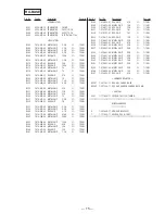
Страница 13: ... 057 00 METAL CHIP 2 2K 5 1 10W R340 1 216 065 91 RES CHIP 4 7K 5 1 10W R341 1 216 113 00 METAL CHIP 470K 5 1 10W R342 1 216 106 00 METAL CHIP 240K 5 1 10W R343 1 216 099 00 METAL CHIP 120K 5 1 10W R344 1 216 092 00 RES CHIP 62K 5 1 10W R345 1 216 084 00 METAL CHIP 30K 5 1 10W R346 1 216 077 00 RES CHIP 15K 5 1 10W R347 1 216 070 00 METAL CHIP 7 5K 5 1 10W R348 1 216 089 91 RES CHIP 47K 5 1 10W R3...

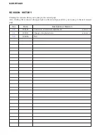
Страница 14: ... revised page Also clicking the version at the upper right on the revised page allows you to jump to the next revised page Ver Date Description of Revision 1 2 2001 01 Correction of electrical adjustments 1 1 2000 11 Change of exploded view 1 0 2000 06 New ENG 01023 ENG 00019 ...

Отзывы: