


Screen Displays
23
P
repa
ra
ti
ons
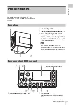
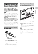
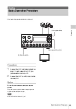
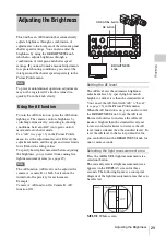
Various information is displayed on the front
panel display of the unit.
The type of information displayed varies
depending on the DISPLAY screen.
Each press of the DISPLAY button switches the
DISPLAY screen as follows: DISPLAY1
t
DISPLAY2
t
DISPLAY3
t
DISPLAY1.
In the DISPLAY2 and DISPLAY3 screens, the
current settings for the camera selected with the
CAMERA SEL button will be displayed
separately for each camera.
You can also turn the backlight of the front panel
display on/off by holding down the DISPLAY
button for one or more seconds.
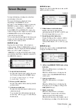
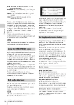
DISPLAY1 screen
Displays the output format, AE, and picture
profile settings. When CAMERA SEL is set to A
or BOTH, “camA” is displayed. When CAMERA
SEL is set to B, “camB” is displayed.
“REMOTE” is displayed when the unit is being
operated remotely from a computer connected to
the REMOTE connector.
1.
Output format indication
Displays the output format which is based on
the Country setting in the OTHERS menu.
For details on output formats, see “Output
Format Settings” (page 22).
2.
Picture profile indication
Displays the number of the currently selected
picture profile.
3.
AE function indication
Displays the currently selected AE function
adjustment mode.
You can select the AE function adjustment
mode using “AE”
in the Picture
Profile menu.
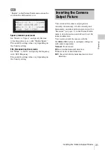
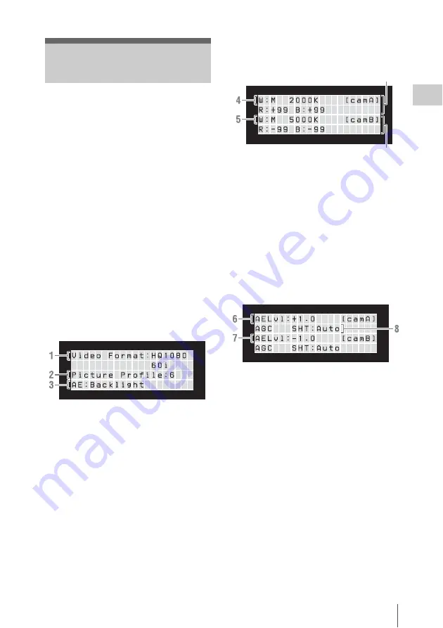
DISPLAY2 screen
Displays the current white balance mode, and R
and B gain offset settings.
4.
White balance mode indications
Displays the current white balance
adjustment mode (W:M, W:P, or ATW) and
the color temperature
5.
R and B gain offset indication
Display the R gain offset adjusted with the
RED knob and the B gain offset adjusted
with the BLUE knob (–99 to +99)
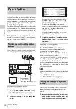
DISPLAY3 screen
Displays the current AE level, BRIGHTNESS,
total gain, and shutter settings.
6.
AE level and BRIGHTNESS knob setting
indication
When the AE function is on, displays the
current AE level.
When the AE function is off, displays the
setting value of the BRIGHTNESS knob
(–50 to +21).
7.
Total gain indication
When the AE function is on, displays
“AGC”.
When the AE function is off, displays the
total gain as set according to setting of the
BRIGHTNESS knob.
8.
Shutter indication
When the AE function is on, displays
“SHT:AUTO” (because the auto shutter
function is turned on automatically).
When the AE function is off, displays one of
the following, according to the shutter mode
Screen Displays
Camera A
Camera B
Содержание MCC3000MT
Страница 56: ...Sony Corporation ...


