background image

32

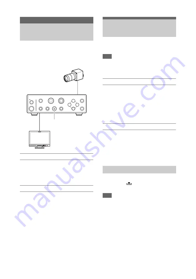
When the unit starts up, camera picture output 
being shot on this unit is output from the video 
output connectors (VIDEO, S VIDEO, HDMI, 
SDI) on the rear panel of the CCU.

Viewing camera picture output

Connect a video monitor to any of the video 
output connectors.

For details, see “Connecting Video Monitors” (page 
27).

Adjusting camera picture output

You can automatically adjust the brightness.

To automatically adjust the brightness

Press the AUTO button to activate the indicator.
The AE function is now activated. The gain value 
and shutter speed change automatically, and the 
brightness is adjusted automatically at all times. 

To adjust the brightness manually, turn the AE 
function off. For details, see “Adjusting the 
Brightness” (page 34)
.

You can also activate saved Picture Profiles to 
adjust camera picture output.

For details, see “Picture Profile” (page 36).

The white balance must be adjusted according to 
the color temperature of the light source.

Note

When [Fluorescein] is set to [On] in the 
[Function] menu, the white balance will be set to 
fluorescein mode settings and cannot be adjusted.

Preset mode

The color temperature is set to a preset value 
(3200K under factory default settings) in this 
mode.
Use this mode when you do not have time to 
adjust the white balance or when you want to 
shoot with a fixed white balance configured in the 
picture profile settings.

Offset mode

The camera picture output color balance can be 
changed by adjusting the R and B gain values in 
this mode 

(see page 33)

.

To enable offset mode, set [White Balance] > 
[Preset On/Off] to [Off] and [Offset On/Off] to 
[On] in the [Picture] menu.

You can adjust the white balance automatically 
by pressing the 

 WHITE button on the CCU 

front panel.

Note

Auto white balance is not available in the 
following cases.
• When preset mode is enabled
• When [Fluorescein] is set to [On] in the 

[Function] menu

• When the image being shot is a color bar

1

Place a white object (such as a piece of 
white paper) under the same conditions 
as the light source illuminating the 
subject, and zoom in so that the entire 
screen is filled with the white object.

Shooting

Shooting

AUTO button

Adjusting the White 
Balance

Executing auto white balance

Содержание MCC-1000MD

Страница 1: ... 2018 Sony Corporation HD Video Camera Instructions for Use Before operating the unit please read this manual thoroughly and retain it for future reference MCC 1000MD 4 742 987 11 1 2018 11 ...

Страница 2: ...equipment must only be connected to a supply mains with protective earth Warning This unit has no power switch To disconnect the main power unplug the power plug When installing the unit incorporate a readily accessible disconnect device in the fixed wiring or connect the power plug to an easily accessible socket outlet near the unit Do not position the ME equipment where it is difficult to unplug...

Страница 3: ...ation Service Center 1 800 222 7669 or http www sony com For customers in the U S A Caution Federal law United States of America restricts this device to sale by or on the order of a licensed healthcare practitioner For customers in Canada This unit has been certified according to Standard CAN CSA C22 2 No 60601 1 This symbol indicates the equipotential terminal which brings the various parts of a...

Страница 4: ...devices may increase the leakage current 4 For all peripheral devices connected to the unit that operate on commercial power supplies and do not comply with IEC 60601 1 standards incorporate an isolation transformer that complies with IEC 60601 1 standards and connect to the commercial power supply via the transformer 5 The unit generates uses and may radiate radio frequency energy If it is not in...

Страница 5: ...by Sony Corporation may result in increased emissions or decreased immunity of the MCC 1000MD List of cables used for EMC test Type of cable Specifications CCMC SA15 cable 15 m shielded CCMC EA05 cable 5 m shielded Guidance and manufacturer s declaration electromagnetic emissions The MCC 1000MD is intended for use in the electromagnetic environment specified below The customer or the user of the M...

Страница 6: ...spital environment IEC 61000 4 5 2 kV line s to earth 2 kV common mode Voltage dips short interruptions and voltage variations on power supply input lines IEC 61000 4 11 0 UT 100 dip in UT for 0 5 1 cycles a 40 UT 60 dip in UT for 5 cycles 70 UT 30 dip in UT for 25 30 cycles a for 0 5 sec 0 UT 100 dip in UT for 250 300 cycles a for 5 sec 0 UT 100 dip in UT for 0 5 1 cycles a 40 UT 60 dip in UT for...

Страница 7: ...601 test level Compliance level Electromagnetic environment guidance Portable and mobile RF communications equipment should be used no closer to any part of the MCC 1000MD including cables than the recommended separation distance calculated from the equation appliance to the frequency of the transmitter Recommended separation distance Conducted RF IEC 61000 4 6 3 Vrms 150 kHz to 80 MHz outside ISM...

Страница 8: ...ction from structures objects and people a Field strengths from fixed transmitters such as base stations for radio cellular cordless telephones and land mobile radios amateur radio AM and FM radio broadcast and TV broadcast cannot be predicted theoretically with accuracy To assess the electromagnetic environment due to fixed RF transmitters an electromagnetic site survey should be considered If th...

Страница 9: ... 1 2 2007 IEC 60601 1 2 2014 150 kHz to 80 MHz d 1 2 P 80 MHz to 800 MHz d 1 2 P 800 MHz to 2 5 GHz d 2 3 P 150 kHz to 80 MHz d 1 2 P 80 MHz to 2 7 GHz d 2 0 P 0 01 0 12 0 12 0 23 0 12 0 20 0 1 0 38 0 38 0 73 0 38 0 63 1 1 2 1 2 2 3 1 2 2 0 10 3 8 3 8 7 3 3 8 6 3 100 12 12 23 12 20 For transmitters rated a maximum output power not listed above the recommended separation distance d in meters m can ...

Страница 10: ...tion 18 Hz 27 V m 27 V m 430 470 MHz GMRS 460 FRS 460 FM 5 kHz deviation 1 kHz sine 28 V m 28 V m 704 787 MHz LTE Band 13 17 Pulse modulation 217 Hz 9 V m 9 V m 800 960 MHz GSM 800 900 TETRA 800 iDEN 820 CDMA 850 LTE Band 5 Pulse modulation 18 Hz 28 V m 28 V m 1 700 1 990 MHz GSM 1800 CDMA 1900 GSM 1900 DECT LTE Band 1 3 4 25 UMTS Pulse modulation 217 Hz 28 V m 28 V m 2 400 2 570 MHz Bluetooth WLA...

Страница 11: ...ould use the following type of power cord Customers in other countries or regions should use the power cord prescribed by their country or region Note Grounding reliability can only be achieved when the equipment is connected to an equivalent receptacle marked Hospital Only or Hospital Grade Warning The apparatus shall not be exposed to dripping or splashing No objects filled with liquids such as ...

Страница 12: ...mportant information and complete terms and conditions of Sony s limited warranty applicable to this product For the customers in Europe Sony Professional Solutions Europe Standard Warranty and Exceptions on Standard Warranty Please visit http www pro sony eu warranty for important information and complete terms and conditions For the customers in Korea SONY LIMITED WARRANTY Please visit http bpen...

Страница 13: ...d other discomfort Use with electrosurgical knives and similar devices If this unit is used together with an electrosurgical knife etc the picture may be disturbed warped or otherwise abnormal as a result of strong radio waves or voltages from the device This is not a malfunction When you use this unit simultaneously with a device from which strong radio waves or voltages are emitted confirm the e...

Страница 14: ...ddenly rises moisture may form on the outer surface of the unit and or inside of the unit This is known as condensation If condensation occurs turn off the unit and wait until the condensation clears before operating the unit Operating the unit while condensation is present may damage the unit Phenomena specific to the CMOS image sensor The following phenomena are specific to the CMOS image sensor...

Страница 15: ...ecautions concerning heat generation by the unit Be careful during operation of the unit as the metal surfaces of the unit may become hot Generation of heat during operation of the unit is not a malfunction ...

Страница 16: ...onnecting the camera cable to the camera head 25 Connecting the camera cable to the CAMERA connector on the CCU 25 Connecting an extension cable 26 Connecting Video Monitors 27 Start up 28 Turning the power on 28 Entering standby mode 28 Output Format Settings 29 Setting the output format 29 Setting the output signal format 29 Output signal types 31 Shooting Shooting 32 Adjusting the White Balance...

Страница 17: ...ndard setting values factory default settings 39 Menu Display and Detailed Settings Menu Structure and Layers 40 Menu structure 40 Menu layers 40 Basic Menu Operations 41 Menu List 43 Picture menu 43 Function menu 48 White Black Adjust menu 49 System menu 50 Information menu 51 System Operation Examples Using the Foot Switch 52 Connecting the foot switch 52 Set the functions to use 52 Using Two Ca...

Страница 18: ... Exmor R is trademark of Sony Corporation The terms HDMI and HDMI High Definition Multimedia Interface and the HDMI Logo are trademarks or registered trademarks of HDMI Licensing LLC in the United States and other countries All other trademarks are the property of their respective owners Further the or symbol is not used in the text ...

Страница 19: ...ogressive format allowing you to capture details and movement in videos with greater clarity than in interlaced format Additionally synchronized operation of two of these units allows you to shoot 3D videos Cutting edge camera technologies 1 2 8 type Exmor R CMOS sensor Equipped with three Exmor R CMOS sensors this camera allows shooting in Full HD Compact lightweight camera head The camera head i...

Страница 20: ...e Two camera support for 3D shooting Using the built in 3D SYNC IN OUT connectors you can synchronize the image signals from two cameras to shoot 3D images Intuitive control via the front panel The BRIGHTNESS RED and BLUE knobs on the front panel provide an intuitive way to adjust the picture ...

Страница 21: ...ra on a wall ceiling or tripod 3 Camera cable connector 20 pin page 25 1 1 on standby switch page 28 2 LOCK lock button page 53 3 WHITE white balance button page 32 4 PROFILE Picture Profile selection button page 36 5 FREEZE still image button page 35 6 MENU button page 41 7 ENTER confirm button page 41 8 V v B b cursor button page 41 9 BRIGHTNESS brightness adjustment knob page 35 Part Names and ...

Страница 22: ... confirm that the reduced risk now conforms to IEC 60601 1 standards Caution Do not come into contact with the terminals of the rear panel connectors and patients at the same time Doing so may result in a generation of voltage that can be harmful to patients if the unit is malfunctioning Always disconnect the power cord before connecting and disconnecting connectors 1 CAMERA connector page 25 2 3D...

Страница 23: ...23 9 HDMI output connector HDMI type A page 27 10 SDI output connector 1 2 BNC type page 27 ...

Страница 24: ... mm 3 16 in or less Mounting a lens with a maximum protrusion of 4 2 mm 3 16 in or more may damage the internal mechanism of the camera head 1 Remove the lens mount cap 2 Align the threads of the lens mount and camera mount and insert the lens 3 Slowly turn the lens clockwise to securely attach it to the camera Preparations Lens Mounting Mounting the lens Lens mount surface 4 1 mm 3 16 in or less ...

Страница 25: ...hing it straight in taking care not to bend the pins Make sure connectors are securely inserted A loose connection may result in noise When removing a connector be sure to hold it by the connector itself and not the cable 1 Align the positioning marks on the camera cable connector and the round camera cable plug and then push the plug in 2 Turn cable connector ring to tighten the connection Note D...

Страница 26: ...and then push them together 2 Turn cable connector ring to tighten the connection Notes Use only one extension cable Operation is not guaranteed when more than one extension cable is used When used in conjunction with a standard CCMC SA15 cable the total cable length can be extended to up to 20 m 65 6 ft Connecting an extension cable Connector ring Positioning marks CCMC EA05 Extension cable Camer...

Страница 27: ...om a 16 9 image and output as a 4 3 image Notes Before connecting the cables make sure that the unit is turned off When connecting video monitors only do so using a direct cable Using a conversion adapter may cause the camera picture output to output incorrectly Connecting Video Monitors Video Monitors S VIDEO IN a 75 Ω coaxial cable b HDMI cable c S connector cable Note We recommend using Sony HD...

Страница 28: ...a picture output will appear on the video monitor Note When you start the unit after replacing the camera head startup may take longer than usual Press the 1 on standby switch again The unit enters standby mode and the indicator turns orange Note If you disconnect the power cord without setting the unit to standby mode setting information may be lost Start up Turning the power on Video monitor see...

Страница 29: ...e ENTER button The output method is now set Note When you change the Region setting the SDI and HDMI output signal formats will return to factory default values Be sure to reconfigure the output signal formats if necessary Set the output signal format according to the connected video monitor in the System menu s SDI Video Format or HDMI Video Format option 1 Display the System menu select SDI Vide...

Страница 30: ...press the ENTER button Tip If the video monitor does not support the selected output signal format the confirmation message cannot be operated i e the message will not appear In such cases the switching operation will be canceled in 15 seconds and the output signal format will revert to the format from before the change 4 Press the MENU button to close the menu screen ...

Страница 31: ...nals are shown in the table below 1 The left and right edges of a 16 9 image are cropped and the image is output as a 4 3 image Output signal types Region SDI output HDMI output VIDEO output S VIDEO output NTSC 1080 59 94p 1080 59 94i 1080 59 94p 1080 59 94i 480 59 94p NTSC1 PAL 1080 50p 1080 50i 1080 50p 1080 50i 576 50p PAL1 ...

Страница 32: ... the Function menu the white balance will be set to fluorescein mode settings and cannot be adjusted Preset mode The color temperature is set to a preset value 3200K under factory default settings in this mode Use this mode when you do not have time to adjust the white balance or when you want to shoot with a fixed white balance configured in the picture profile settings Offset mode The camera pic...

Страница 33: ...te balance Using the knobs Turn the RED or BLUE knob to adjust the R or B white gain offset value Turning the RED knob clockwise strengthens red while turning it counterclockwise strengthens green Turning the BLUE knob clockwise strengthens blue while turning it counterclockwise strengthens yellow You can reset the offset value to 0 factory default setting by holding down the RED or BLUE knobs for...

Страница 34: ...mal settings The AE function adjustment level AE level the adjustment mode and the upper and lower limit values can all be set in the Picture menu by going to Exposure Mode and selecting Auto see page 43 Setting the AE level The AE level sets the automatic brightness level adjustment by specifying how much brighter or darker it is than the standard level Perform sets using the BRIGHTNESS knob or u...

Страница 35: ...clockwise will darken the image lower gain or a faster shutter speed You can reset the AE level to factory default settings by holding down the BRIGHTNESS knob for one second or longer To output a still image Press the FREEZE button on the CCU front panel to output camera images as a still image When still image output is enabled the FREEZE button lights To return to normal picture Press the FREEZ...

Страница 36: ... hue for only the color fluorescing due to the excitation light with Color Hue in the Picture menu You can customize settings to match shooting conditions and save these as a picture profile to load when necessary Simply select the picture profile to shoot at your preferred image quality settings You can save up to six different picture profiles on this unit No 1 to No 6 There are six factory pres...

Страница 37: ...he menu screen and in the Picture menu select Profile and then press the ENTER button 2 Select Select and press the ENTER button 3 Select the profile to load and press the ENTER button The unit will adjust the image quality according to the selected profile 4 Press the MENU button to close the menu screen Registering a picture profile When you change the settings after a picture profile is activat...

Страница 38: ...ttings 5 Once settings are complete press the MENU button to close the menu screen You can specify the selectable range of picture profiles that are available when you press the PROFILE button on the front panel to select a picture profile The selectable range of picture profiles specified here will also be used when picture profiles are assigned to a foot switch 1 Press the MENU button The menu s...

Страница 39: ... Shutter Mode High Speed High Speed High Speed High Speed High Speed High Speed Shutter Speed 1 60 1 60 1 60 1 60 1 60 1 60 White Balance Preset On Off Off Off Off Off Off Off Preset 3200 3200 3200 3200 3200 3200 Offset On Off On On On On On On Red Gain Offset 0 0 0 0 0 0 Blue Gain Offset 0 0 0 0 0 0 Enhance Noise Reduction Sharpness On Off On On On On On On Sharpness Level 50 50 50 0 0 0 Sharpnes...

Страница 40: ...uality and other settings related to shooting page 43 Function menu Adjust the settings related to camera functions page 48 White Black Adjust menu Adjust settings for the color balance page 49 System menu Adjust settings related to output format and output signal page 50 Information menu Displays the unit serial number and software version page 51 1 Appears only when Region is set to NTSC Menu Di...

Страница 41: ...buttons to select a menu to set 2 Press the ENTER button or b button The cursor will move to the right side of the menu item area Tip Press the B button to return to the next higher menu layer 3 Press the V v buttons to select a menu item 4 Press the ENTER button or b button The current setting value appears When a menu item is selected with an On Off or switching only option without a detailed it...

Страница 42: ...es will appear depending on the menu item In that case press the B b buttons to set the value The gray circle on the slider indicates the setting value before the change and the blue circle indicates the current setting value Tip When a slider is displayed holding down the B b buttons increases the incremental speed at which the value changes allowing you to set your target value faster Hiding the...

Страница 43: ...Sensitivity Off On Select whether to set the maximum gain to a high value and operate with high sensitivity Off Do not operate with high sensitivity On Operate with high sensitivity When in Auto mode Area Full Large Middle Spot Slit Specify the metering area for exposure adjustment Full Entire screen Large Equal to Full vertically and 75 of Full horizontally Middle 75 of Large both vertically and ...

Страница 44: ... 12 dB Set the maximum gain value for AE adjustment When in Manual mode Gain 0 to 30 dB Select the gain Shutter Mode High Speed Slow Select the electronic shutter mode High Speed Set the shutter speed in seconds Use this when you want to shoot fast moving subjects without blurring or when you want to adjust the brightness Slow Set the shutter speed in cumulative frames Use this when you want to sh...

Страница 45: ...ther to set the color temperature to the preset value When Preset On Off is set to On Preset 2100 to 10000K 3200K Set the preset value for the color temperature in 100 K steps Offset On Off Off On Select whether to adjust the R and B gain values manually When Preset On Off is set to Off and Offset On Off is set to On Red Gain Offset 99 to 0 to 99 Adjust the red level Blue Gain Offset 99 to 0 to 99...

Страница 46: ...Mode Auto Manual Auto Automatically calculate the optimal brightness level at which to start compression and degree of compression based on the brightness level of the image being shot Manual Manually adjust the brightness level at which to start compression and the degree of compression When Knee Mode is set to Manual Knee Point 50 to 109 90 Adjust the brightness level at which to start compressi...

Страница 47: ...reduce noise Color Image vividness settings Saturation 99 to 0 to 99 Adjust the vividness Hue 99 to 0 to 99 Adjust the hue Low Key Saturation 99 to 0 to 99 Adjust the vividness of dark areas of the image Profile Picture Profile operations Select No 1 No 2 No 3 No 4 No 5 No 6 Load the selected picture profile Copy To No 1 No 2 No 3 No 4 No 5 No 6 Copy the setting values of the currently selected pi...

Страница 48: ...luorescein mode settings Off On Switch between activated deactivated for fluorescein mode which reduces blue light during fluorescein shooting Off Deactivated On Activated Center Marker Center marker display Off On Select whether to display the center marker Image On Screen Graphics overlay setting Off On Select whether to display graphics on the output image during front panel operations Off Do n...

Страница 49: ...ng adjustment R G B Select R G B Select the channel for which to adjust shading H Saw 99 to 0 to 99 Correct H Saw shading H Para 99 to 0 to 99 Correct H Para shading V Saw 99 to 0 to 99 Correct V Saw shading V Para 99 to 0 to 99 Correct V Para shading Auto Black Balance Auto black balance execution Perform auto black balance Master Black Level Master black level adjustment 99 to 0 to 99 Adjust the...

Страница 50: ... 1080 50i 576 50p NTSC Setup NTSC setup settings Available only when Region is set to NTSC Off On Select whether to add 7 5 setup to the signals output from the VIDEO and S VIDEO connectors when Region is set to NTSC Remote 1 Settings for remote contact switch connector 1 None Freeze Fluorescein Picture Profile Flip HV Flip All Digital Zoom Select a function to execute using the foot switch connec...

Страница 51: ...e image flip function as follows Do not flip t horizontal and vertical flip t do not flip Flip All Switches the status of the image flip function as follows Do not flip t horizontal flip t vertical flip t horizontal and vertical flip t do not flip Digital Zoom Enables disables digital zoom All Reset Resets all settings on the unit to their factory default values However the Region setting will not...

Страница 52: ...tereo mini jack Set the functions to use with the foot switch For details on the function controlled by the foot switch see System menu page 50 1 Press the MENU button The menu screen will appear 2 In the System menu select Remote 1 or Remote 2 and press the ENTER button When connected to remote contact switch connector 1 select Remote 1 and when connected to remote contact switch connector 2 sele...

Страница 53: ...o keep 3D standards in mind so as not to adversely effect human subjects Use camera cables of equal length for both of the cameras You can lock button and knob operations on the front panel of the CCU by pressing the LOCK button on the front panel The LOCK button lights while operations are locked When a button or knob other than the 1 on standby switch or LOCK button is operated while operations ...

Страница 54: ...le that connects from the unit to a computer or details about RS 232C control contact Sony service representative Controlling the Unit with a Computer Computer Video monitor Camera head C a D sub 9 pin remote control cable b 75 Ω coaxial cable c For details on connecting to the camera head see page 25 b a ...

Страница 55: ...om the camera The camera head and CCU are not securely connected Check the connection with the camera head The System menu s Region option setting differs from your video monitor settings Correctly set the System menu s Region setting see page 50 You can also change the Region setting as follows To set to NTSC Press the LOCK button while holding down the MENU and V buttons To set to PAL Press the ...

Страница 56: ... front panel except the power indicator will blink rapidly When the following messages appear all of the LED indicators on the front panel except the power indicator will blink Errors Warnings Error display Message Explanation System Error XX XX stands for the error number When this message appears contact Sony service representative with the error number Warning display Message Explanation Camera...

Страница 57: ...ox 200 62 264 mm approx 7 7 8 2 1 2 10 1 2 in Supplied items See Package Configuration page 19 Image device 1 2 8 type Exmor R CMOS image sensor RGB 3CMOS type Effective pixels 1920 H 1080 V Lens mount C mount Sensitivity F13 Typical At 1080 59 94i 89 9 reflection 2000 lx F20 Typical At 1080 59 94i 89 9 reflection 2000 lx High Sensitivity is ON Picture S N 63 dB Y Typical Horizontal resolution 100...

Страница 58: ...gainst electric shock Class I Protection against harmful ingress of water Ordinary Degree of safety in the presence of a flammable anesthetic mixture with air or with oxygen or nitrous oxide Not suitable for use in the presence of a flammable anesthetic mixture with air or with oxygen or nitrous oxide Mode of operation Continuous Design and specifications are subject to change without notice Notes...

Страница 59: ...26 F Features 19 Flip 48 Fluorescein 48 Foot switch 52 Freeze 48 Function menu 48 H HDMI Video Format 50 I Information menu 51 L Lens Mounting 24 M Menu Basic menu operations 41 Menu controls 41 Menu List 43 N NTSC Setup 50 O Output signal types 31 P Picture menu 43 Picture Profile 36 Copy 37 Registering activating 36 Reset 38 Precautions for Use 13 Profile 47 R Region 50 Remote 1 50 Remote 2 51 S...

Страница 60: ...60 V Version Information 51 Video Monitors Connecting 27 W White balance 32 45 White Black Adjust menu 49 ...

Страница 61: ...Sony Corporation 1 7 1 Konan Minato ku Tokyo 108 0075 Japan ...

Отзывы: