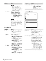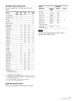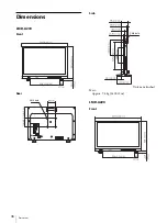
Adjustment Using the Menus
23
Note
When [Auto SDI Switch] is set to on, the following
functions turn off.
[Time Code]
[Closed Caption]
[Blending]
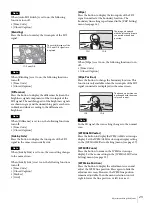
Press the button to overlay the two inputs of the SDI
signal.
Note
When [Blending] is set to on, the following functions
turn off.
[Time Code]
[Closed Caption]
[Difference]
Press the button to display the differences between the
brightness signal components of the two inputs of the
SDI signal. The matching parts of the brightness signals
are shown in gray and the unmatching parts are shown
in black and white according to the difference in
brightness.
Note
When [Difference] is set to on, the following functions
turn off.
[Time Code]
[Closed Caption]
[Side by Side]
Press the button to display the two inputs of the SDI
signal in the same screen side by side.
Note
When [Side by Side] is set to on, the scan setting changes
to the normal scan.
When [Side by Side] is set to on, the following functions
turn off.
[Time Code]
[Closed Caption]
[Marker]
[Grid]
[Wipe]
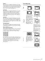
Press the button to display the two inputs of the SDI
signal connected at the boundary location. The
boundary line setting is performed in the [P&P Setting]
menu (see page 26).
Note
When [Wipe] is set to on, the following functions turn
off.
[Time Code]
[Closed Caption]
[Wipe Position]
Press the button to change the boundary location. This
function is only available when the two inputs of the SDI
signal connected are displayed in the same screen.
Note
In the 2K signal, the scan setting changes to the normal
scan.
[WFM/ALM/Vector]
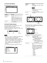
Press the button to display the WFM/ALM/vectorscope
display. Set the WFM/ALM/vectorscope display setting
in the [WFM/ALM/Vector Setting] menu (see page 27).
[WFM/VS Zoom]
Press the button to zoom in the WFM/vectorscope
display. Set the zoom setting in the [WFM/ALM/Vector
Setting] menu (see page 29).
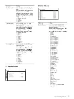
[WFM Line Position]
Press the button to display the adjustment screen and
adjust the WFM line position. Press again to hide the
adjustment screen. However, the WFM line position
remains adjustable. Turn the menu selection control
right to lower the line position, or left to raise it.
The overlaid images of the
SDI1 and SDI2 signals are
displayed.
SDI1 and SDI2
The image is displayed
with the left and right parts
connected at boundary
position.
SDI1
SDI2
The boundary position can
be changed with the menu
selection control.
SDI1
SDI2
Содержание LMD-A170
Страница 39: ...Sony Corporation ...


