


- 13 -
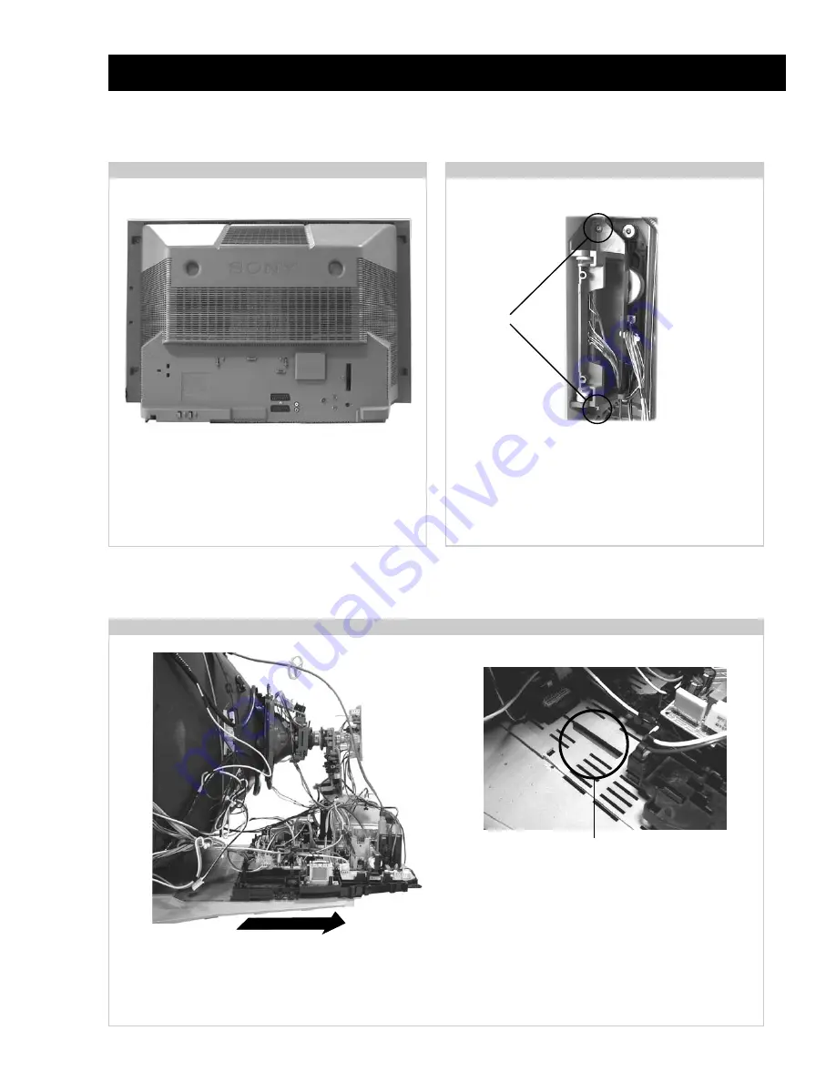
Remove the rear cover fixing screws indicated and withdraw
the rear cover from the beznet.
SECTION 2
DISASSEMBLY
To remove lift the main bracket rear slightly and slide the
chassis away from the beznet. Ensure that the interconnecting
leads are released from their purse locks to prevent damage
being caused.
When refitting the chassis ensure that the main
bracket is located in the beznet guide slots before
sliding the chassis forwards. Refit the
interconnecting leads in their respective purse locks.
Remove the two screws fixing the user control module to the
side of the set. The control module can then be removed by
sliding it towards the rear of the set allowing access to the H2
Board.
2-1. Rear Cover Removal
2-2. Side Control Module Removal
2-3. Chassis Removal and Refitting
Screws
=>
=>
=>
<=
<=
<=
<=
<=
<=
<=
Содержание KD-28DX40U
Страница 29: ... 29 A Schematic Power Supply Deflection Small Signal Audio Amp page 1 2 KD 28 32DX40U 9 927 411 01 ...
Страница 30: ... 30 A Schematic Power Supply Deflection Small Signal Audio Amp page 2 2 KD 28 32DX40U 9 927 411 01 ...
Страница 34: ... 34 A1 Schematic Digital Front End Processing ...


