PCS-G50/G50P
4-27
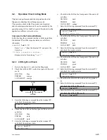
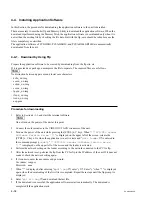
4-2-4. AUX IN Signal Check
1.
Refer to Section 4-1-2, and start the Diag mode.
2.
Connect the unit’s AUDIO OUT (MIXED) connector
and AUDIO IN AUX connector with the audio cable.
3.
Enter the following command from the terminal PC,
and check the response status.
command> auxmute 1
↓
command> linemute 1
↓
command> audioin 0
↓
command> sendeccmd 10a84000
↓
EC DSP : transmit command = 0x10a84000
command> sendeccmd 10a9000a
↓
EC DSP : transmit command = 0x10a9000a
command> sendeccmd 10a20000
↓
EC DSP : transmit command = 0x10a20000
command> getecsts
EC DSP : return code = 0xXXXXXXX
4.
Check that the last response status “
0xXXXXXXX
” is
within specification.
Specification:
0x8F0D180
±
20%
(
0x7270E00
to
0xABA9500
)
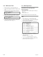
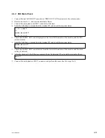
4-2-5. LINE IN Signal Check
1.
Refer to Section 4-1-2, and start the Diag mode.
2.
Connect the unit’s AUDIO OUT (MIXED) connector
and AUDIO IN LINE connector with the audio cable.
3.
Enter the following command from the terminal PC,
and check the response status.
command> auxmute 1
↓
command> linemute 1
↓
command> audioin 1
↓
command> sendeccmd 10684000
↓
EC DSP : transmit command = 0x10684000
command> sendeccmd 1069000a
↓
EC DSP : transmit command = 0x1069000a
command> sendeccmd 10620000
↓
EC DSP : transmit command = 0x10620000
command> getecsts
EC DSP : return code = 0xXXXXXXX
4.
Check that the last response status “
0xXXXXXXX
” is
within specification.
Specification:
0x8F0D180
±
20%
(
0x7270E00
to
0xABA9500
)
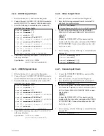
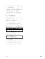
4-2-6. Video Output Check
1.
Refer to Section 4-1-2, and start the Diag mode.
2.
Enter the following command from the terminal PC,
and check the response status.
command> cb cenc
↓
Color Bars on VOA( 1, 2 ) CENC screen
3.
Check that the color-bar signal is output from the
VIDEO OUT AUX and VIDEO OUT MONITOR1/2
connectors.
n
Connect the VIDEO OUT AUX connector and the
monitor with the video cable, and connect the VIDEO
OUT MONITOR1/2 connector and the monitor with
the S video cable.
4.
After checking, enter the following command from the
terminal PC.
command> videovfp 4 0
↓
command> cb off
↓
command> videoin 0 0
↓
command> videoin 1 0
↓
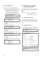
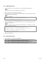
4-2-7. Camera Input Check
1.
Connect the VIDEO IN CAMERA connector of the
unit and the camera.
2.
Refer to Section 4-1-2, and start the Diag mode.
3.
Enter the following command from the terminal PC.
command> videoin 1 1
↓
4.
Check that the picture, from the camera connected to
the VIDEO IN CAMERA connector from the VIDEO
OUT AUX and VIDEO OUT MONITOR1/2 connec-
tors, is output.
n
Connect the VIDEO OUT AUX connector and the
monitor with the video cable, and connect the VIDEO
OUT MONITOR1/2 connector and the monitor with
the S video cable.
5.
After checking, enter the following command from the
terminal PC.
command> videoin 0 0
↓
Содержание Ipels PCS-G50
Страница 6: ......
Страница 16: ......
Страница 26: ......
Страница 34: ......
Страница 170: ......
Страница 186: ......
Страница 191: ...PCS G50 G50P 8 7 8 7 CPU 382 B SIDE SUFFIX 12 13 A B C D 1 2 3 4 CPU 382 CPU 382 ...
Страница 198: ......
Страница 199: ......
Страница 200: ...Printed in Japan Sony Corporation 2005 6 22 2005 PCS G50 UC PCS G50P CE E 9 968 181 01 ...

