– 88 –
•
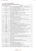
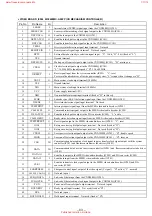
PANEL BOARD IC601 TMP88CS76F-6005 (FLUORESCENT INDICATOR TUBE DRIVER, KEY CONTROL)
Pin No.
Pin Name
I/O
Description
1
SIRCS
I
Remote control signal input from the remote control receiver (IC602)
2
JOG-A
I
Jog dial pulse input from the rotary encoder (S601 JOG) (A phase input)
3
LED SCK
O
Serial data transfer clock signal output to the LED driver (IC604)
4
LED LAT
O
Serial data latch pulse signal output to the LED driver (IC604)
5
LED DATA
O
Serial data output to the LED driver (IC604)
6
PAD LAT
O
Not used (open)
7
L SEL
O
LED selection signal output terminal
8
JOG-B
I
Jog dial pulse input from the rotary encoder (S601 JOG) (B phase input)
9
VOL-A
I
Jog dial pulse input from the rotary encoder (S602 VOLUME) (A phase input)
10
VOL-B
I
Jog dial pulse input from the rotary encoder (S602 VOLUME) (B phase input)
11
KEY0
I
Key input terminal (A/D input) (S625 to S630 and S632 to S635)
REC PAUSE/START, HI-DUB, CD SYNC, CD LOOP, DISPLAY, SPECTRUM ANALYZER,
SELECT, RETURN, PREV, NEXT keys input
12
KEY1
I
Key input terminal (A/D input) (S611 to S624) SYNC BASS, SYNC EQ, KARAOKE
PON/MPX, CD NON-STOP, CINEMA SPACE SURROUND, DBFB, ENTER/NEXT, +
)
, –
0
, GROOVE, CD FLASH, REPEAT STEREO/MONO, PLAY MODE DOLBY NR, EDIT
DIRECTION TUNER MEMORY keys input
13
KEY2
I
Key input terminal (A/D input) (S638 to S642 and S751 to S757)
TIMER SELECT, P FILE MEMORY, GEQ CONTROL, FILE SELECT, EFFECT, I/
u
,
(STANDBY) POWER SAVE DEMO, DISC 1/2/3, DISC SKIP EX-CHANGE,
§
keys input
14
KEY3
I
Key input terminal (A/D input) (S643 to S651)
TUNER/BAND,
(
P
CD,
p
,
(
TAPE B,
9
TAPE B,
(
TAPE A,
9
TAPE A,
FUNCTION, CLOCK/TIMER SET keys input
15
GRAD L2
O
Not used (open)
16
S LOW FREQ
(BPF0)
I
Spectrum analyzer drive (super low frequency) signal input from the spectrum analyzer band-
pass filter (IC603) (for 40 Hz)
17
BPF1
I
Spectrum analyzer drive (low frequency) signal input from the spectrum analyzer band-pass filter
(IC603) (for 100 Hz)
18
BPF2
I
Spectrum analyzer drive (low and middle frequency) signal input from the spectrum analyzer
band-pass filter (IC603) (for 400 Hz)
19
BPF3
I
Spectrum analyzer drive (middle and high frequency) signal input from the spectrum analyzer
band-pass filter (IC603) (for 2 kHz)
20
BPF4
I
Spectrum analyzer drive (high frequency) signal input from the spectrum analyzer band-pass filter
(IC603) (for 6 kHz)
21
ALL BAND
(L+R)
I
Spectrum analyzer drive signal input from the spectrum analyzer band-pass filter (IC603)
(for VACS, non-stop signal)
22
WAKE UP
O
Wakeup control signal output to the system controller (IC501) “H” active
23
VSS
—
Ground terminal
24
VASS
—
Ground terminal (for A/D conversion)
25
VAREF
I
Reference voltage (+5V) input terminal (for A/D conversion)
26
VDD
—
Power supply terminal (+5V)
27 to 32
G18 to G13
O
Grid drive signal output to the fluorescent indicator tube (FL601)
33 to 40
G12 to G5
O
Grid drive signal output to the fluorescent indicator tube (FL601)
41
VDD
—
Power supply terminal (+5V)
42 to 44
G4 to G2
O
Grid drive signal output to the fluorescent indicator tube (FL601)
45
G1
O
Grid drive signal output to the fluorescent indicator tube (FL601)
46 to 67
S1 to S22
O
Segment drive signal output to the fluorescent indicator tube (FL601)
68
VKK
—
Power supply terminal (–30V) (for fluorescent indicator tube drive)
www.freeservicemanuals.info
1/11/16
Published in Heiloo, Holland.

