


16
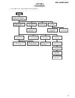
HCD-SC5/SC6/SC8
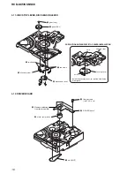
3-11. DISC STOP LEVER, DISC SENSOR LEVER
chassis (top)
hole
Install the disc stop lever so that the both holes
are aligned.
hole
1
gear (cap)
3
two claws
5
two hooks
6
disc stop lever
disc stop lever
4
disc sensor lever
PRECAUTION DURING DISC STOP LEVER INSTALLATION
2
gear (IDL L)
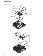
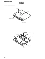
3-12. DRIVER BOARD
3
Remove soldering
from the two points.
2
three screws
(+BVTP 2.6
×
8)
5
DRIVER board
4
motor (pully) assy
1
belt (MOT)
Содержание HCD-SC5
Страница 125: ...125 HCD SC5 SC6 SC8 MEMO ...


