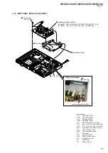


HBD-E2100/E3100/E3200/E4100/E6100
33
SECTION 5
TROUBLESHOOTING
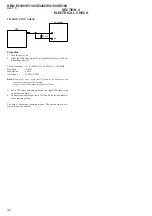
Power Check Flow (1/2)
Check that the output voltages of the switching regulator
(SWR1) are the following value.
CN301 pin 1: 12 V (FEUNSW12V)
CN301 pin 2: 12 V (ICUNSW12V)
CN301 pin 3: 12 V (UNSW12V)
Check that the following fuses and thermistor are not damaged.
TH802/F802/F201/F202/F203
Ye
s
Ye
s
C
heck
each
vol
tage w
ith r
ef
er
ence
to the
sc
hematic
diagrams,
and check
that ther
e is
no
pr
oblem
in them.
Check the
related IC
on
the
MB1002
board.
Ye
s
C
heck
the
fo
llow
ing
pow
er
contr
ol
si
gnal
in the power on state.
(Nor
mally voltage:
+3
.3
V)
MB1002 board
IC801
pin
36
to
38
(PCON
T1 to
PCON
T3)
Pin 25
(PCONT
_F
L)
Ye
s
The power is turned on.
A
No
Yes
Pr
otect
mode happened “PROTECT”
dis
play appear
s
on
fluor
es
cent
tube.
No
Ye
s
C
heck
that har
nes
s is
ins
er
ted nor
m
ally
at
CN101
Remove harness
of
CN
101, CN
4,
FFC
CN
3505.
Measure switching
supply board CN
101
pin4 <-> pin1,
(nor
mal voltage
>
30V)
Ye
s
Ye
s
AMP boar
d
damage.
Exchange the
complete AMP
board.
Check
that harness is
inse
rted normally at
CN
301
and
C
N
202. When
har
nes
s
is ins
er
ted nor
m
ally, exchange
the
switching regulator (SWR1).
No
Exchange the
damaged f
us
e
or
thermistor.
Exchange the
complete MB1002 board, when the power is not turned on,
even if
you
exchange f
us
es
.
No
Pow
er
s
upply IC
is
damaged. Exchange
the
pow
er
s
upply IC.
No
Exchange
the
complete MB1002 board.
No
No
Ins
er
t nor
mally the har
nes
s and
pow
er
O
N
again.
No
Sw
itching s
upply
boar
d
damage. Exchange the
complete
sw
itching s
upply
boar
d.


