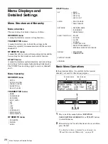
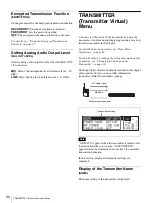
Sony DWR-R01D Скачать руководство пользователя страница 32

32

RF REMOTE Menu

For details on how to operate the transmitter, refer to 
the operating instructions supplied with the 
transmitter.

3

Rotate the jog dial to select YES, and then press the 
dial.

The receiver starts searching for transmitters and then 
displays the names of transmitters with which pairing 
is possible.
During the search, pressing any operation key on the 
receiver will cancel pairing mode.

4

Rotate the jog dial to select the transmitter to be paired 
with from among those indicated, and then press the 
dial to enter the setting.

The receiver starts to communicate with the selected 
transmitter and the wireless remote control condition 
appears in the display. The condition level (indicated 
by 

) goes up and the remote control function 

becomes operative.


If the receiving channel (CH) configured on the receiver is 
a channel for which use with the wireless remote control 
function is restricted on the transmitter side, the 
UNMATCH screen appears.
In such cases, change the receiving channel on the 
receiver. If you want to use the restricted channel, set 
REMOTE to OFF in the transmitter’s menu to release the 
channel restriction, and manually configure the 
transmitter’s channel.

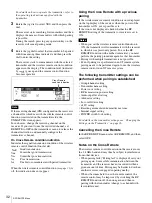
On Cross Remote condition indication

Indicates the signal transmission condition of the wireless 
remote control function (four levels).

: Good transmission

: Somewhat good transmission

: Somewhat poor transmission
: Poor transmission
: Unable to communicate with paired transmitter

When the wireless remote control function 

(see page 31)

 is 

off, this indication does not appear.

Using the Cross Remote with a previous 

pairing 

If the wireless remote control condition icon is displayed 
on the top display of the receiver when the power of the 
transmitter is ON, use is possible as is.
If the icon is not displayed, check whether the RF 
REMOTE setting of the transmitter or receiver is set to 
ON.


• When you set the wireless remote control function to 

ON, the transmitter will communicate with the receiver 
to which it was previously paired. To use the RF 
REMOTE function with another transmitter, you must 
perform the pairing procedure again for that transmitter.

• Pairing with multiple transmitters is not possible.
• Even if pairing was performed in an ST remote system, 

pairing needs to be performed again to use the wireless 
remote control in an NT remote system.

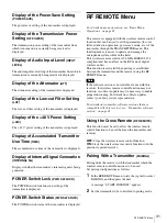
The following transmitter settings can be 

performed when pairing is established:

• Group/channel setting
• Transmitter name setting
• Power save setting
• RF transmission power setting
• Audio input level setting
• Attenuator setting
• Low-cut filter setting
• +48V setting
• Resetting accumulated transmitter use time
• Internal signal setting
• POWER switch lock setting

For details on the transmitter settings, see “Changing the 
Settings on the Transmitter” on page 36.

Cancelling the Cross Remote

In the RF REMOTE menu, select RF REMOTE, and then 
select OFF.

Notes on the Cross Remote

The wireless remote control function on the receiver uses 
the 2.4 GHz band and may thus be subject to interference 
from other devices.
• When pairing fails (“Pairing fail” is displayed), carry out 

pairing again. Successful communication between the 
transmitter and the receiver has not occurred within a 
given amount of time. Pairing may be harder to do when 
another receiver is engaged in pairing nearby. 

• When it becomes hard to use the remote control, the 

remote control may be improved by switching the RF 
REMOTE function off, then on again, and then re-
pairing with the transmitter (change to a channel with 
less interference).

Note

Cross Remote 

condition indication

Notes

Содержание DWR-R01D

Страница 1: ...retain it for future reference DWR R01D 4 177 125 17 1 2010 Sony Corporation The supplied CD ROM includes Operating Instructions for the DWR R01D Digital Wireless Receiver English Japanese French German Italian and Spanish versions and the frequency lists English and Japanese versions in PDF format For more details see Using the CD ROMs on page 10 ...

Страница 2: ...s been damaged in any way such as power supply cord or plug is damaged liquid has been spilled or objects have fallen into the apparatus the apparatus has been exposed to rain or moisture does not operate normally or has been dropped To reduce the risk of fire or electric shock do not expose this apparatus to rain or moisture To avoid electrical shock do not open the cabinet Refer servicing to qua...

Страница 3: ...nce is normally required The local district office of Industry Canada should therefore be contacted When the operation of the device is within the broadcast band the licence is issued on no interference no protection basis with respect to broadcast signals This Class B digital apparatus complies with Canadian ICES 003 Afin de réduire les risques d incendie ou d électrocution ne pas exposer cet app...

Страница 4: ... 2 this device must accept any interference received including interference that may cause undesired operation IMPORTANT NOTE To comply with the FCC RF exposure compliance requirements no change to the antenna or the device is permitted Any change to the antenna or the device could result in the device exceeding the RF exposure requirements and void user s authority to operate this device This dev...

Страница 5: ...unt u vinden op http www compliance sony de För kunder i Europa Härmed intygar Sony Corporation att denna DWR R01D står I överensstämmelse med de väsentliga egenskapskrav och övriga relevanta bestämmelser som framgår av direktiv 1999 5 EG För ytterligare information gå in på följande hemsida http www compliance sony de Para clientes na Europa Sony Corporation declara que este DWR R01D está conform...

Страница 6: ...ovnej webovej adrese http www compliance sony de Za stranke v Evropi Sony Corporation izjavlja da je ta DWR R01D v skladu z bistvenimi zahtevami in ostalimi relevantnimi določili direktive 1999 5 ES Za podrobnosti vas naprošamo če pogledate naURL http www compliance sony de For the customers in the U S A SONY LIMITED WARRANTY Please visit http www sony com psa warranty for important information an...

Страница 7: ... 30 TRANSMITTER Transmitter Virtual Menu 30 Display of the Transmitter Name NAME 30 Display of the Power Save Setting POWER SAVE 31 Display of the Transmission Power Setting RF POWER 31 Display of Audio Input Level INPUT LEVEL 31 Display of the Attenuator ATT 31 Display of the Low cut Filter Setting LCF 31 Display of the 48 V Power Setting 48V 31 Display of Accumulated Transmitter Use Time TIME 31...

Страница 8: ...ime TIME 36 Internal Signal Setting INTERNAL SG 36 POWER Switch Lock Setting PWR SW LOCK 36 Block Diagram 37 When the Alert Indicator Lights 38 Error Messages 39 Troubleshooting 40 Important Notes on Operation 41 Notes on Using the Receiver 41 On cleaning 41 Specifications 42 Carrier Frequencies and Channel Steps 43 ...

Страница 9: ...s system with analog wireless system making the channel setting easier in such cases Building up wireless remote control system according to system scale Digital wireless transmitters can be remotely controlled while checking their status on the display of the DWR R01D You can also use the supplied PC control software to enable remote control from a PC According to the scale and purposes of the sy...

Страница 10: ...must be installed in the PC For details see Installing the software on page 10 Adobe Reader Version 6 0 or higher must be installed on your computer in order to read the User s Guide contained on the CD ROM For details see Using the CD ROM manual on page 11 Operating conditions of the software For details on operating conditions of the software refer to the Wireless Studio User s Guide stored on t...

Страница 11: ...Features in the Windows Control Panel then select Wireless Studio from the list and then delete it Opening the installed files Click Start and select All Programs Sony and Digital Wireless Microphone System and then click one of the following displayed items Wireless Studio Wireless Studio software Wireless Studio User s Guide User s Guide in PDF format Supplied CD ROM Digital Wireless Receiver Th...

Страница 12: ...om the L channel of the headphones and audio from channel 2 is output from the R channel 1 Audio from channel 1 is output from the L and R channels of the headphones 2 Audio from channel 2 is output from the L and R channels of the headphones 1 2 Audio from channel 1 and 2 are mixed to be output L and R channels of the headphones d VOLUME monitor channel selection monitor volume control Press to c...

Страница 13: ...al output sync indication Indicates sync status of the signal output from the DIGITAL OUT connectors INT Output signal is in sync with the internal clock EXT Output signal is in sync with the signal input from the WORD SYNC IN connector e Audio level meter Indicates the level of audio signal input to the transmitter The segments indicating below the reference input level of the transmitter appear ...

Страница 14: ...RF radio reception level meters Indicates the level of the signal input from the ANTENNA a b IN connector The number of segments that light up depends on the input level l Antenna selection indication Indicates the antenna currently selected by the diversity function 2 Controls The control areas for channel 1 and channel 2 are identical a ALERT alert indicator Lights up red when error is detected ...

Страница 15: ...Ne touchez pas le connecteur LAN directement avec vos mains Le transfert d électricité statique peut entraîner un dysfonctionnement de l appareil Par mesure de sécurité ne raccordez pas le connecteur pour le câblage de périphériques pouvant avoir une tension excessive à ce port Suivez les instructions pour ce port Berühren Sie den LAN Anschluss nicht direkt mit den Händen Durch elektrostatische En...

Страница 16: ...ntenna booster Cable loss between antenna and this unit Antenna attenuator setting dB 0 dB or less Reference signal loss examples For details on gain of antenna booster refer to the operating instructions supplied with the antenna The cable loss may differ depending on the manufacturer of the cables The rated resistance of ANTENNA a b IN connectors is 50 Ω If the cable with 75 Ω resistance is used...

Страница 17: ...1D without installing in the rack Attach the supplied four feet to the bottom of this unit as illustrated below To install the DWR R01D in the rack be sure to remove the attached feet Rack DWR R01D Screws B M5 12 Screws B M5 12 Foot Pin Attach the feet into the holes on this unit and then fix the feet by pushing the pins into the holes on the feet ...

Страница 18: ...nit we recommend using optional AN 820A or AN 01 UHF antennas For narrow service areas however you can also use the supplied whip antennas When using the supplied whip antennas be sure to verify your service area beforehand The supplied whip antennas can be attached to the front or rear panel of the unit Front panel attachment 1 Insert the supplied antenna mounts with BNC connectors into the front...

Страница 19: ...ables 50 Ω 60 cm or longer to connect the antenna mounts with BNC connectors to the ANTENNA a b IN connectors on the rear panel of the unit Rear panel attachment Attach the supplied whip antennas to the ANTENNA a b IN connectors on the rear panel Whip antenna supplied ...

Страница 20: ...ansmitters 1 UHF antennas 1 When 41 DWR R01D units are used up to 82 transmitters can be used 2 Up to 41 DWR R01D units can be used by incorporating optional WD 850 units 3 When connecting DWR R01D units in cascade set ANT ATT a b to 0dB and ANT DC OUT to OFF on any DWR R01D unit that is not directly connected to the antenna 3 ...

Страница 21: ...System Configuration Examples Usage Example of Antenna Divider Example of a system that connects a total of 41 units 82 channels in cascade via a separately sold WD 850 WD 850 sold separately UHF antennas ...

Страница 22: ...ecommend cascade connections We recommend using a word clock divider Synchronization system example 1 This system connects the master word clock signal in cascade via the WORD SYNC OUT connector of this device Set the 75 Ω termination switch of only the DWR R01D unit at the end of the cascade connection to ON Synchronization system example 2 This system divides the master word clock signal with a ...

Страница 23: ...system each DWR R01D unit uses one channel of radio wave When more transmitters are used in the system communication congestion may occur resulting in slow response on the controlled devices If you plan to use six or more transmitters operation in NT remote system using the optional RMU 01 is recommended Note Mixer or I O box Up to six transmitters UHF antennas To a wall outlet DWR R01D 1 1 Use of...

Страница 24: ...o cover wider area For details on how to install the RMU 01 refer to the Operating Instructions supplied with the RMU 01 Mixer or I O box To a wall outlet UHF antennas RMU 01 2 Hub PC PoE PoE Transmitters 1 DWR R01D 3 1 When 41 DWR R01D units are used up to 82 transmitters can be used 2 Up to nine RMU 01 units can be installed to expand the NT remote operation area 3 Up to 41 DWR R01D units can be...

Страница 25: ...l function is restricted on the transmitter side the UNMATCH screen appears In such cases change the receiving channel on the receiver If you want to use the restricted channel set REMOTE to OFF in the transmitter s menu to release the channel restriction and manually configure the transmitter s channel About operation when using with dedicated digital channel plan When performing multi channel op...

Страница 26: ...o move the cursor to CLEAR CH SCAN indication and then press the dial A message START SCAN appears 3 Rotate the jog dial to select YES and then press the dial Scanning starts Empty channels within the specified channel group GP are searched When scanning finishes detected empty channels are listed in the order with less interference 4 Rotate the jog dial to select the channel that you want to use ...

Страница 27: ... ENCRYPTION indication and then press the dial 2 Rotate the jog dial to select SECURE KEY and then press the dial 3 Exchanging the encryption key The receiver searches for a transmitter that it has been paired with After the receiver detects the transmitter the transmitter exchanges the encryption key with the receiver and encrypted transmission begins When the RF REMOTE function see page 31 is of...

Страница 28: ...enu TRANSMITTER menu RF REMOTE menu UTILITY menu Basic Menu Operations In the procedure below the controls for the receiver channel 1 are used for illustration purposes 1 Press one of the menu buttons RECEIVER TRANSMITTER RF REMOTE or UTILITY button to select the menu 2 Rotate the jog dial to select the item to be set and then press the dial For details on items contained in each menu see Menu Str...

Страница 29: ...ters are explained Underlined items are the factory settings Group channel Selection GP CH Set the group and channel to receive See Carrier Frequencies and Channel Steps on page 43 for factory settings For details see Selecting the Group Channel on page 25 Active Channel Scanning Function ACTIVE CH SCAN The active channel scan function operates For details see Using the Active Channel Scan Functio...

Страница 30: ...sing the transmitter virtual menu and displaying metadata received from the transmitter in the display For details on menu operation see Basic Menu Operations on page 28 For details on how to change the setting information of the transmitter see Changing the Settings on the Transmitter on page 36 The Sony digital wireless transmitter sends not only digital audio signals but also various other info...

Страница 31: ...be used to set the parameters low cut filter attenuation operation power save mode etc of the transmitter through the TRANSMITTER menu This function makes it easier to operate and manage the microphone system while in the field This wireless remote control is 2 4 GHz IEEE802 15 4 compliant and has no effect on the RF band of digital wireless audio This function is activated when pairing is establi...

Страница 32: ...of the receiver when the power of the transmitter is ON use is possible as is If the icon is not displayed check whether the RF REMOTE setting of the transmitter or receiver is set to ON When you set the wireless remote control function to ON the transmitter will communicate with the receiver to which it was previously paired To use the RF REMOTE function with another transmitter you must perform ...

Страница 33: ...ng shows the US model display All the items in the UTILITY menu can be set by using the controls on the receiver channel 1 The UTILITY menu settings are applied to both receiver channels Items Related to Signal Reception RF submenu Frequency band setting BAND Selects the frequency band that the transmitter uses See Carrier Frequencies and Channel Steps on page 43 for factory settings Antenna atten...

Страница 34: ...delay times for receiver channels 1 and 2 The delay times for receiver channels 1 and 2 may be different when the DWR R01D is used with two digital wireless transmitters of differing models By setting this compensation function to ON in such cases you can automatically adjust the receiver channel with the shorter audio signal delay time to match the channel with the longer delay When adjusting the...

Страница 35: ...rnal sync signal word clock is not possible ON OFF Items Related to Display DISPLAY submenu Setting the brightness of the display BRIGHTNESS Ten levels of brightness can be selected for the organic light emitting diode display The selectable settings are the following Dark 1 2 3 4 5 6 7 8 9 10 Bright Automatic dimming of the display DIMMER MODE The organic light emitting diode display can be set t...

Страница 36: ...is also no longer transmitted For this reason NO DATA appears for all items in the TRANSMITTER menu except for SLEEP in the POWER SAVE indication Transmission Power Setting RF POWER You can change the transmission power of the transmitter Audio Input Level Setting INPUT LEVEL Allows you to change the transmitter s audio input level setting This function may not be supported by some transmitters At...

Страница 37: ...37 Block Diagram Block Diagram Digital wireless tuner 1 Digital wireless tuner 2 Divider Digital Signal Processing Terminate 75 ohms D A Divider ...

Страница 38: ...ere is a problem with the operation channel plan Check whether another external signal is in use The RF indicator is lit in orange The signal input level of the antenna is 80 dBµ or higher Multi channel synchronous operation may be affected Try one of the following Try using the transmitter located away from the antenna Increase the ANT ATT a b setting value of the receiver If the ANT ATT a b sett...

Страница 39: ...m the PHONES terminal exceeds the maximum allowable current or the terminal has short circuited ANTENNA OVER CURRENT DC outputs from the ANTENNA IN connectors exceed the maximum allowable current or the connectors have short circuited CPU EEP ROM NG The data of the CPU EEP ROM is not correct RF EEP ROM NG The data of the RF EEP ROM is not correct ...

Страница 40: ...mitter is turned off Jamming radio waves are being received Set the channel whose RF indicator on the receiver does not light up and then set that same channel on the transmitter When two or more transmitters are being used change to another channel group that is unaffected by jamming radio waves When doing this the clear channel scan function is useful see page 26 Two or more transmitters are set...

Страница 41: ...r the finish Transmitter software version If the software version is not suitable for use with this receiver the wireless remote control and encrypted transmission functions may not function Refer to the following tables for transmitter software versions that are compatible with this receiver A software update may be necessary to enable proper functioning For details on software updates contact yo...

Страница 42: ...AC European model 230 V AC Power consumption 22 W Operating temperature 0 to 50 C 32 to 122 F Storage temperature 20 to 60 C 4 to 140 F Dimensions unit mm inches Mass Approx 4 1 kg 9 lb 1 oz including the attached antenna Wireless remote control 2 4 GHz IEEE802 15 4 compliant LAN 10 100 connector RJ 45 modular jack 1 100BASE TX IEEE802 3u compliant 10BASE T IEEE802 3 compliant Supplied accessories...

Страница 43: ...t available TV38 41 614 125 637 875 MHz U4250 TV42 45 638 125 661 875 MHz 00 4201 638 125 MHz TV46 49 662 125 685 875 MHz TV50 51 686 125 697 875 MHz Model No Frequency band Frequency Group channel factory setting CE3338 TV33 35 566 025 590 000 MHz 00 3301 566 125 MHz TV36 37 590 025 606 000 MHz TV38 40 606 025 630 000 MHz CE4248 TV42 44 638 025 662 000 MHz 00 4201 638 125 MHz TV45 47 662 025 686 ...

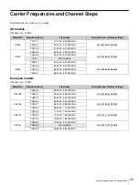
Страница 44: ...44 Carrier Frequencies and Channel Steps ...

Страница 45: ......

Отзывы: