


7-3
7-4 E
5. Checking Component Video Output Y
(MB-85 BOARD)
<Purpose>
This checks component video output Y. If it is incorrect, correct
brightness will not be attained when connected to, for instance,
projector.
Mode
Video level adjustment in test mode
Signal
Color bars
Test point
COMPONENT VIDEO OUT (Y)
connector (75
Ω
terminated)
Instrument
Oscilloscope
Specification
1.0 ± 0.1 Vp-p
Checking method:
1) Confirm that the Y level is 1.0 ± 0.1 Vp-p.
Figure 7-5
6. Checking S Video Output S-C (MB-85 BOARD)
<Purpose>
This checks whether the S-C satisfies the NTSC Standard. If it is
not correct, the colors will be too dark or light.
Mode
Video level adjustment in test mode
Signal
Color bars
Test point
CN005 pin
5
Instrument
Oscilloscope
Specification
286 ± 50 mVp-p
Connection:
Checking method:
1) Confirm that the S-C burst is 286 ± 50 mVp-p.
Figure 7-6
7-3. ADJUSTMENT RELATED PARTS ARRANGEMENT
MB-85 BOARD (SIDE A)
HS-030SF BOARD (SIDE A)
1.0 ± 0.1 Vp-p
286 ± 50 mVp-p
4
5
100
µ
F
75
Ω
±
1%
100k
±
1%
CN005
+
Oscilloscope
1
2
27
28
CN005
RV401
VIDEO LEVEL ADJ
1
1
7
6
CN202
CN203
Содержание DVP-S533
Страница 6: ...1 1 SECTION 1 GENERAL This section is extracted from in struction manual 3 867 038 11 DVP S533D ...
Страница 7: ...1 2 ...
Страница 8: ...1 3 ...
Страница 9: ...1 4 ...
Страница 10: ...1 5 ...
Страница 11: ...1 6 ...
Страница 12: ...1 7 ...
Страница 13: ...1 8 ...
Страница 14: ...1 9 ...
Страница 15: ...1 10 ...
Страница 16: ...1 11 ...
Страница 17: ...1 12 ...
Страница 18: ...1 13 ...
Страница 19: ...1 14 1 14 E ...
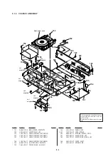
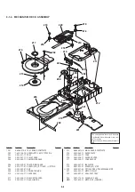
Страница 23: ...2 4 2 11 INTERNAL VIEW DC motor loading 1 541 632 11 Optical pick up KHM 220AAA J1RP 8 820 081 03 ...
Страница 34: ...DVP S533D 4 3 4 4 4 1 FRAME SCHEMATIC DIAGRAM FRAME 1 SCHEMATIC DIAGRAM FRAME 1 2 ...
Страница 35: ...DVP S533D FRAME 2 SCHEMATIC DIAGRAM 4 5 4 6 FRAME 2 2 ...
Страница 53: ...DVP S533D 4 41 4 42 AU 212 AUDIO SCHEMATIC DIAGRAM Ref No AU 212 board 2 000 series AUDIO AU 212 1 2 ...