


1-15
DVP-NS72HP/NS77H/NS77HP/NS78H/NS78HP
59
Settings
and Adjustments
Notes
• To view the best picture quality, set this setting to
“(1920
×
1080i) HD
” or “(1920
×
1080i) HD.”
• “(1920
×
1080i) HD
” and “(1920
×
1080i) HD”
are effective only when you set “HDMI
RESOLUTION” to “1920x1080i” and “TV
TYPE” to “16:9.”
• If you set this setting to “(1920
×
1080i) HD
” or
“(1920
×
1080i) HD,” wipe, rotation, and zoom
function are not available.
• If you want to use wipe, rotation, and zoom
function; sets this setting to “SD
,” “HD
,”
or “HD.”
• If you set this setting to “(1920
×
1080i) HD
” or
“(1920
×
1080i) HD,” next image appears after
black mute.
• HDMI signal will stop momentarily during
loading or unloading DATA CD or DATA DVD
disc.
◆
YC
B
C
R
/RGB (HDMI)
Selects the type of HDMI signal output from
HDMI OUT jack.
Notes
• If the playback picture becomes distorted, set
“YC
B
C
R
” to “RGB.”
• If the HDMI OUT jack is connected to equipment
with a DVI jack, “RGB” signals will be
automatically output even when you select
“YC
B
C
R
”.
◆
SCREEN SAVER
The screen saver image appears when you
leave the player in pause or stop mode for 15
minutes, or when you play a CD, or DATA
CD (MP3 audio)/DATA DVD (MP3 audio)
for more than 15 minutes. The screen saver
will help prevent your display device from
becoming damaged (ghosting). Press
H
to
turn off the screen saver.
◆
BACKGROUND
Selects the background colour or picture on
the TV screen when the player is in stop mode
or while playing a CD, or DATA CD (MP3
audio)/DATA DVD (MP3 audio).
◆
LINE
Selects video signals output from the LINE
(RGB)-TV jack on the rear panel of the
player.
Notes
• If your TV does not accept S video or the RGB
signals, no picture will appear on the TV screen,
even if you select “S VIDEO” or “RGB
(COMPONENT OFF).” Refer to the instructions
supplied with your TV.
• If your TV has only one SCART (EURO AV)
jack, do not select “S VIDEO.”
• When you select “RGB (COMPONENT OFF),”
you cannot use the PROGRESSIVE button or the
COMPONENT VIDEO OUT jacks.
• You cannot select “RGB (COMPONENT OFF)”
when the player outputs progressive signals
(page 17).
SD
Displays standard definition
picture with black frame.
HD
Displays high definition picture
with black frame.
HD
Displays high definition picture
without black frame.
(1920
×
1080i)
HD
Displays high definition picture
with black frame at 1920
×
1080
pixels.
(1920
×
1080i)
HD
Displays high definition picture
without black frame at
1920
×
1080 pixels.
YC
B
C
R
Outputs YC
B
C
R
signals.
RGB
Outputs RGB signals.
ON
Turns on the screen saver.
OFF
Turns off the screen saver.
JACKET
PICTURE
The jacket picture (still picture)
appears, but only when the
jacket picture is already
recorded on the disc (CD-
EXTRA, etc.). If the disc does
not contain a jacket picture, the
“GRAPHICS” picture appears.
GRAPHICS
A preset picture stored in the
player appears.
BLUE
The background colour is blue.
BLACK
The background colour is
black.
VIDEO
Outputs video signals.
S VIDEO
Outputs S video signals.
RGB
(COMPONENT
OFF)
Outputs RGB signals and no
component video signals.
,
continued
60
◆
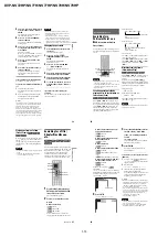
4:3 OUTPUT
This setting is effective only when you set
“TV TYPE” in “SCREEN SETUP” to
“16:9.” Adjust this to watch 4:3 aspect ratio.
If you can change the aspect ratio on your TV,
change the setting on your TV, not the player.
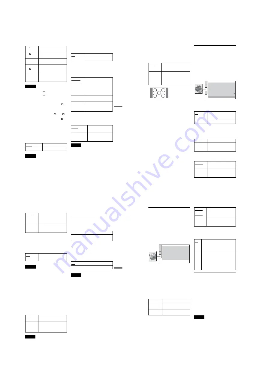
Custom Settings
(CUSTOM SETUP)
Use this to set up playback related and other
settings.
Select “CUSTOM SETUP” in the Setup
Display. To use the display, see “Using the
Setup Display” (page 56).
The default settings are underlined.
◆
AUTO POWER OFF
Switches the Auto Power Off setting on or
off.
◆
AUTO PLAY
Switches the Auto Play setting on or off. This
function is useful when the player is
connected to a timer (not supplied).
◆
DIMMER
Adjusts the lighting of the front panel display.
FULL
Select this when you can
change the aspect ratio on your
TV.
NORMAL
Select this when you cannot
change the aspect ratio on your
TV. Shows a 16:9 aspect ratio
signal with black bands on left
and right sides of the image.
16:9 aspect ratio TV
ON
The player enters standby mode
when left in stop mode for more
than 30 minutes.
OFF
Switches this function off.
OFF
Switches this function off.
ON
Automatically starts playback
when the player is turned on by
a timer (not supplied).
BRIGHT
Makes the lighting bright.
DARK
Makes the lighting dark.
AUTO
DARK
Makes the lighting dark if you
do not operate the player or
remote for a short while.
CUSTOM SETUP
AUTO PLAY:
DIMMER:
OFF
BRIGHT
AUTO
PAUSE MODE:
OFF
TRACK SELECTION:
ON
AUTO POWER OFF:
ON
MULTI-DISC RESUME:
OFF
HDMI CONTROL:
Registration Code
DivX:
ON
LANGUAGE FOLLOW:
61
Settings
and Adjustments
◆
PAUSE MODE (DVDs only)
Selects the picture in pause mode.
◆
TRACK SELECTION (DVD VIDEO only)
Gives the sound track which contains the
highest number of channels priority when you
play a DVD VIDEO on which multiple audio
formats (PCM, MPEG audio, DTS, or Dolby
Digital format) are recorded.
Notes
• When you set the item to “AUTO,” the language
may change. The “TRACK SELECTION” setting
has higher priority than the “AUDIO” settings in
“LANGUAGE SETUP” (page 57).
• If you set “DTS” to “OFF” (page 63), the DTS
sound track is not played even if you set “TRACK
SELECTION” to “AUTO.”
• If PCM, DTS, MPEG audio, and Dolby Digital
sound tracks have the same number of channels,
the player selects PCM, DTS, MPEG, and Dolby
Digital sound tracks in this order.
◆
MULTI-DISC RESUME (DVD VIDEO/
VIDEO CD only)
Switches the Multi-disc Resume setting on or
off. Resume playback can be stored in
memory for up to 6 different DVD VIDEOs/
VIDEO CDs (page 27).
Note
If you run Quick Setup, Multi-disc Resume settings
stored in memory may return to the default settings.
◆
DivX
Displays the registration code for this player.
For more information, go to
http://www.divx.com/vod
on the Internet.
◆
HDMI CONTROL
Switches the HDMI CONTROL setting
on or off.
◆
LANGUAGE FOLLOW
Switches the languages of the DVD player
to the same as the current TV OSD
language.
You cannot select this when “HDMI
CONTROL” is set to “OFF.”
Notes
• Turn off any display before using this function.
• The OSD language for player keeps if the TV’s
language cannot be supported.
AUTO
The picture, including subjects
that move dynamically, is
output with no jitter. Normally,
select this position.
FRAME
The picture, including subjects
that do not move dynamically,
is output in high resolution.
OFF
No priority given.
AUTO
Priority given.
ON
Stores the resume setting in
memory for up to 6 discs.
OFF
Does not store the resume
setting in memory. Playback
restarts at the resume point only
for the current disc in the player.
OFF
Switches this function off.
ON
Allows you to use the HDMI
CONTROL features (page 17).
ON
Switches this function on.
OFF
Switches this function off.
62
Settings for the Sound
(AUDIO SETUP)
“AUDIO SETUP” allows you to set the sound
according to the playback and connection
conditions.
Select “AUDIO SETUP” in the Setup
Display. To use the display, see “Using the
Setup Display” (page 56).
The default settings are underlined.
◆
AUDIO DRC (Dynamic Range Control)
(DVDs only)
Makes the sound clear when the volume is
turned down when playing a DVD that
conforms to “AUDIO DRC.”
This function affects the output from the
following jacks:
– LINE OUT L/R (AUDIO) jacks
– LINE (RGB)-TV jack
– DIGITAL OUT (COAXIAL)/HDMI OUT
jack only when “DOLBY DIGITAL” is set
to “D-PCM” (page 63).
◆
DOWNMIX (DVDs only)
Switches the method for mixing down to 2
channels when you play a DVD which has
rear sound elements (channels) or is recorded
in Dolby Digital format. For details on the
rear signal components, see “Checking the
audio signal format” (page 45). This function
affects the output of the following jacks:
– LINE OUT L/R (AUDIO) jacks
– LINE (RGB)-TV jack
– DIGITAL OUT (COAXIAL)/HDMI OUT
jack when “DOLBY DIGITAL” is set to
“D-PCM” (page 63).
◆
DIGITAL OUT
Selects if audio signals are output via the
DIGITAL OUT (COAXIAL)/HDMI OUT
jack.
Setting the digital output signal
Switches the method of outputting audio
signals when you connect a component such
as an audio component or MD deck with a
digital input jack.
For connection details, see page 19.
Select “DOLBY DIGITAL,” “MPEG,”
“DTS,” and “48kHz/96kHz PCM” after
setting “DIGITAL OUT” to “ON.”
If you connect a component that is
incompatible with the selected audio signal, a
loud noise (or no sound) may be heard from
the speakers, risking damage to your ears or
speakers.
Notes
• The AV SYNC function (page 36) is not effective
if you use the DIGITAL OUT (COAXIAL) jack,
and set “DOLBY DIGITAL,” “MPEG” or “DTS”
to “DOLBY DIGITAL,” “MPEG” or “ON”
respectively.
• The AV SYNC function (page 36) is not effective
if you connect a Dolby Digital or DTS-compliant
device via the HDMI OUT jack, and set “DOLBY
DIGITAL,” “MPEG” or “DTS” to “DOLBY
DIGITAL,” “MPEG” or “ON” respectively.
STANDARD
Normally, select this position.
TV MODE
Makes low sounds clear even if
you turn the volume down.
WIDE
RANGE
Gives you the feeling of being
at a live performance.
AUDIO SETUP
AUDIO DRC:
DIGITAL OUT:
STANDARD
ON
DOWNMIX:
DOLBY SURROUND
DOLBY DIGITAL:
MPEG:
D-PCM
PCM
DTS:
OFF
48kHz/96kHz PCM:
48kHz/16bit
AUDIO (HDMI):
AUTO
DOLBY
SUR-
ROUND
Normally, select this position.
Multi-channel audio signals are
output to 2 channels for enjoying
surround sounds.
NORMAL
Multi-channel audio signals are
downmixed to 2 channels for use
with your stereo.
ON
Normally, select this position. When
you select “ON,” see “Setting the
digital output signal” for further
settings.
OFF
The influence of the digital circuit
upon the analogue circuit is minimal.
If you are using the HDMI OUT jack,
PCM sound will be output depending
on the connected equipment. If the
signal is encrypted for copyright
protection purposes, the signal is only
output as 48 kHz/16 bit PCM.


