Sony DVP-NS72HP Operating Instructions / Manual de instrucciones Скачать руководство пользователя страница 19

1-14

DVP-NS72HP/NS77H/NS77HP/NS78H/NS78HP

55

Enjoying DivX

®

 Vide

os

Selecting a DivX video file

1

After step 2 of “Selecting an album,” 
press ENTER.

The list of files in the album appears. 

2

Press 

X

/

x

 to select a file, and press 

ENTER.

The selected file starts playing.

To stop playback

Press 

x

.

To go to the next or previous page

Press 

C

 or 

c

.

To return to the previous display

Press 

O

 RETURN.

To go to the next or previous DivX video 
file without turning on the above file list

You can select the next or previous DivX 
video file in the same album by pressing 

>

or

.

.

You can also select the first file of the next 
album by pressing 

>

 during playback of 

the last file of the current album. Note that 
you cannot return to the previous album by 
using

.

. To return to the previous album, 

select it from the album list.

z

Hint

If the number of viewing times is preset, you can 
play the DivX video files as many times as the 
preset number. The following occurrences are 
counted:
– when the player is turned off. This includes when 

the player is automatically turned off by the Auto 
Power Off function. Press 

X

 instead of 

x

 when 

you want to stop viewing.

– when the disc tray is opened.
– when another file is played.

56

Settings and Adjustments

Using the Setup Display

By using the Setup Display, you can make 
various adjustments to items such as picture 
and sound. You can also set a language for the 
subtitles and the Setup Display, among other 
things. 
For details on each Setup Display item, see 
pages from 57 to 63.

Note

Playback settings stored in the disc take priority 
over the Setup Display settings and not all of the 
functions described may work.
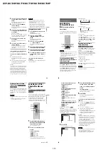
1

Press DISPLAY when the player is 
in stop mode.

The Control Menu appears.

2

Press 

X

/

x

 to select 


(SETUP), then press ENTER.

The options for “SETUP” appear.

3

Press 

X

/

x

 to select “CUSTOM,” 

then press ENTER.

The Setup Display appears.

4

Press 

X

/

x

 to select the setup item 

from the displayed list: 

“LANGUAGE SETUP,” “SCREEN 
SETUP,” “CUSTOM SETUP,” or 
“AUDIO SETUP.” Then press 

ENTER.

The Setup item is selected.
Example: “SCREEN SETUP”

5

Press 

X

/

x

 to select an item, then 

press ENTER.

The options for the selected item appear.
Example: “TV TYPE”

ENTER

DISPLAY

Number 
buttons

( 47 )

STOP

QUICK
CUSTOM
RESET

DVD VIDEO

QUICK

LANGUAGE SETUP

OSD:
MENU:
AUDIO:
SUBTITLE:

ENGLISH
ENGLISH

ORIGINAL

ENGLISH

SCREEN SETUP

TV TYPE:
HDMI RESOLUTION:

YC

B

C

R

/RGB (HDMI):

16:9

AUTO

(1920×1080p)

JPEG RESOLUTION:

HD
YC

B

C

R

SCREEN SAVER:

ON

BACKGROUND:

JACKET PICTURE

LINE:

VIDEO

4:3 OUTPUT:

FULL

Selected item

Setup items

SCREEN SETUP

TV TYPE:
HDMI RESOLUTION:
JPEG RESOLUTION:
YC

B

C

R

/RGB (HDMI):

16:9

4:3 LETTER BOX

SCREEN SAVER:
BACKGROUND:

4:3 PAN SCAN

JACKET PICTURE

ON

LINE:
4:3 OUTPUT:

VIDEO

FULL

16:9

Options

57

Settings

 and Adjustments

6

Press

X

/

x

 to select a setting, then 

press ENTER.

The setting is selected and setup is 
complete.
Example: “4:3 PAN SCAN”

To enter the Quick Setup mode

Select “QUICK” in step 3. Follow from step 
5 of the Quick Setup explanation to make 
basic adjustments (page 23).

To reset all of the “SETUP” settings

1

Select “RESET” in step 3 and press 
ENTER.

2

Select “YES” using 

X

/

x

.

You can also quit the process and return 
to the Control Menu by selecting “NO” 
here.

3

Press ENTER.
All the settings explained on pages 57 to 
63 return to the default settings. Do not 
press

[

/

1

 while resetting the player, 

which takes a few seconds to complete.

Setting the Display or 
Sound Track Language 

(LANGUAGE SETUP)

“LANGUAGE SETUP” allows you to set 
various languages for the on-screen display or 
sound track.

Select “LANGUAGE SETUP” in the Setup 
Display. To use the display, see “Using the 
Setup Display” (page 56).

OSD (On-Screen Display)

Switches the display language on the screen.

MENU (DVD VIDEO only)

You can select the desired language for the 
disc’s menu.

AUDIO (DVD VIDEO only)

Switches the language of the sound track.
When you select “ORIGINAL,” the language 
given priority in the disc is selected.

SUBTITLE (DVD VIDEO only)

Switches the language of the subtitle recorded 
on the DVD VIDEO.
When you select “AUDIO FOLLOW,” the 
language for the subtitles changes according 
to the language you selected for the sound 
track.

z

Hint

If you select “OTHERS 

t

” in “MENU,” 

“SUBTITLE,” or “AUDIO,” select and enter a 
language code from “Language Code List” on 
page 69 using the number buttons.

Note

If you select a language in “MENU,” 
“SUBTITLE,” or “AUDIO” that is not recorded on 
a DVD VIDEO, one of the recorded languages will 
be automatically selected.

Selected setting

SCREEN SETUP

TV TYPE:
HDMI RESOLUTION:

YC

B

C

R

/RGB (HDMI):

4:3 PAN SCAN

AUTO

(1920×1080p)

YC

B

C

R

SCREEN SAVER:

ON

BACKGROUND:

JACKET PICTURE

LINE:

VIDEO

4:3 OUTPUT:

FULL

JPEG RESOLUTION:

HD

LANGUAGE SETUP

OSD:
MENU:
AUDIO:
SUBTITLE:

ENGLISH
ENGLISH

ORIGINAL

ENGLISH

58

Settings for the Display 

(SCREEN SETUP)

Choose settings according to the TV to be 
connected.

Select “SCREEN SETUP” in the Setup 
Display. To use the display, see “Using the 
Setup Display” (page 56).
The default settings are underlined.
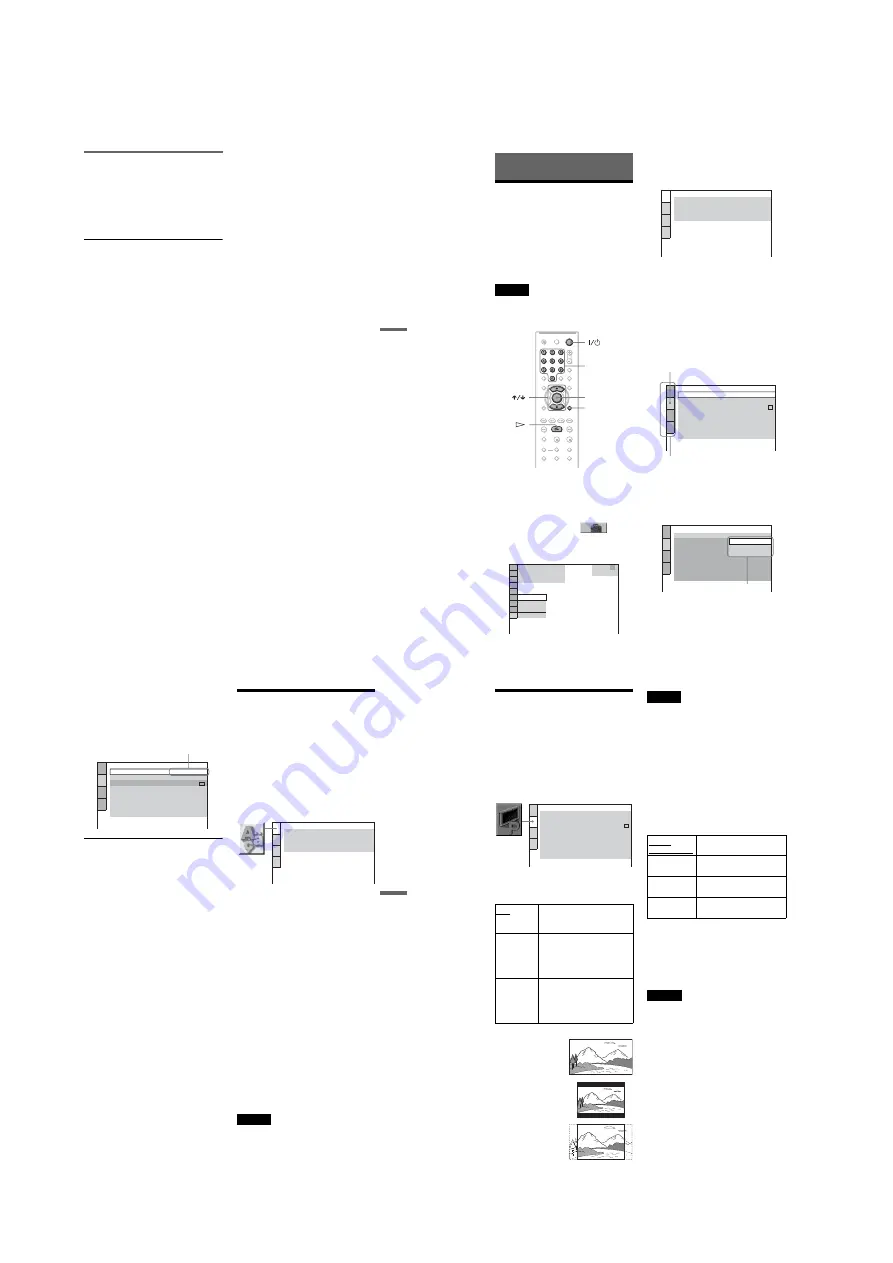
TV TYPE

Selects the aspect ratio of the connected TV 
(4:3 standard or wide).

Note

Depending on the DVD, “4:3 LETTER BOX” may 
be selected automatically instead of “4:3 PAN 
SCAN” or vice versa.

HDMI RESOLUTION

Selects the type of video signals output from 
the HDMI OUT jack. When you select 
AUTO (1920×1080p) (default), the player 
outputs video signals of the highest resolution 
acceptable for your TV. If the picture is not 
clear, natural or to your satisfaction, try 
another option that suits the disc and your 
TV/projector, etc. For details, refer also to the 
instruction manual supplied with the TV/
projector, etc.

To reset the setting 

If the picture does not appear normal or goes 
blank, press 

[

/

1

 to turn off the player, and 

enter “369” using the number buttons on the 
remote, then press 

[

/

1

 to turn on the player 

again.

Notes

• In case of “AUTO (1920×1080p),” the player 

automatically adjusts the video signals that are 
suitable for the TV.
Other cases, the player directly send the signal 
even if TV cannot accept.

• When the HDMI indicator on the front panel 

lights up, images from the LINE OUT (VIDEO) 
jacks are enlarged vertically. (Except when 
720

×

480/576p is selected). 

JPEG RESOLUTION

Selects the type of JPEG resolution so that 
you can enjoy high picture quality via your 
HDMI connection.
You cannot select this when “HDMI 
RESOLUTION” is set to “720

×

480/576p” or 

“TV TYPE” is set to “4:3 LETTER BOX” or 
“4:3 PAN SCAN”.

16:9

Select this when you connect a 
wide-screen TV or a TV with a 
wide mode function.

4:3
LETTER 
BOX

Select this when you connect a 
4:3 screen TV. Displays a wide 
picture with bands on the upper 
and lower portions of the 
screen.

4:3
PAN SCAN

Select this when you connect a 
4:3 screen TV. Automatically 
displays the wide picture on the 
entire screen and cuts off the 
portions that do not fit.

SCREEN SETUP

HDMI RESOLUTION:

YC

B

C

R

/RGB (HDMI):

AUTO

(1920×1080p)

JPEG RESOLUTION:

HD
YC

B

C

R

SCREEN SAVER:

ON

BACKGROUND:

JACKET PICTURE

LINE:

VIDEO

4:3 OUTPUT:

FULL

TV TYPE:

16:9

16:9

4:3 LETTER BOX

4:3 PAN SCAN

AUTO 
(1920x1080p)

Normally, select this.

1920

×

1080i

Sends 1920

×

1080i video 

signals.

1280

×

720p

Sends 1280

×

720p video 

signals.

720

×

480/

576p

Sends 720

×

480/576p video 

signals.

Содержание DVP-NS72HP Operating Instructions / Manual de instrucciones

Страница 1: ...P MX NS78H CND NS78HP E BR Phono jack Y 1 0 Vp p PB PR interlace 1 0 648 Vp p progressive or interlace 2 0 7 Vp p 75 ohms 1 BLACK LEVEL COMPONENT OUT is ON 2 BLACK LEVEL COMPONENT OUT is OFF COMPONENT VIDEO OUT Y PB CB PR CR DVP NS78H AEP UK KR RUS SP TH Phono jack Y 1 0 Vp p PB CB PR CR 0 7 Vp p 75 ohms LINE OUT VIDEO Phono jack 1 0 Vp p 75 ohms S VIDEO OUT DVP NS77H US NS77HP MX NS78H CND NS78HP...

Страница 2: ... part having a return to chassis must not exceed 0 5mA 500 microampers Leakage current can be measured by any one of three methods 1 A commercial leakage tester such as the Simpson 229 or RCA TW 540A Follow the manufacturers instructions to use these instruments 2 Abattery operatedACmilliammeter TheDataPrecision245digital multimeter is suitable for this job 3 Measuring the voltage drop across a re...

Страница 3: ...4 Custom Settings Custom Setup 1 15 Settings for the Sound Audio Setup 1 15 Additional Information 1 16 Troubleshooting 1 16 Self diagnosis Function When letters numbers appear in the display 1 17E Specifications 1 17E 2 DISASSEMBLY 2 1 Upper Case 2 1 2 2 Front Panel Assembly SW 512 Board 2 1 2 3 Loading Assembly 2 2 2 4 Optical Pick Up Device Optical KHM 313CAA C2RP 2 3 2 5 Rear Panel MV Board an...

Страница 4: ...nitializing Setup Data 6 2 6 4 Version Information 6 3 6 5 If Con Self Diagnostic Function 6 3 7 ELECTRICAL ADJUSTMENT 7 1 Power Supply Output Voltage Check 7 1 7 2 Adjustment of Video System 7 2 8 REPAIR PARTS LIST 8 1 Exploded Views 8 1 8 1 1 Main Section 8 1 8 1 2 Mechanism Deck Assembly 8 5 8 2 Electrical Parts List 8 6 ...

Страница 5: ...lever of chuck cam in the direction of arrow D 5E 2 CHILD LOCK DISABLED PROCEDURE When LOCKED appears on the front panel display Child Lock is activated In order to disable it either 1 Press O RETURN ENTER and then 1 on the remote when the player is in standby mode The player turns on and UNLOCKED appears on the front panel display or 2 Disconnect the player from the wall outlet AC power source No...

Страница 6: ...nal Organization for Standardization IEC International Electrotechnical Commission MPEG which compresses audio data 2 DivX is a video file compression technology developed by DivX Inc 3 DivX DivX Certified and associated logos are trademarks of DivX Inc and are used under license 6 This Player Can Play the Following Discs DVD RW DVD RW DVD R DVD R DL DVD R DVD VIDEO and CD logos are trademarks Not...

Страница 7: ...ly is prohibited 8 Guide to Parts and Controls For more information see the pages indicated in parentheses Front panel A 1 on standby button 25 B Disc tray 25 C Front panel display 9 D remote sensor 21 E PROGRESSIVE button 17 F HDMI High Definition Multimedia Interface indicator 16 58 63 Lights up when the HDMI OUT jack is correctly connected to a HDCP High bandwidth Digital Content Protection com...

Страница 8: ...l tracks all albums repeatedly or one title chapter track album file repeatedly A B REPEAT page 33 Specifies the parts you want to play repeatedly CUSTOM PICTURE MODE page 34 Adjusts the video signal from the player You can select the picture quality that best suits the programme you are watching SHARPNESS page 36 Exaggerates the outline of the image to produce a sharper picture AV SYNC page 36 Ad...

Страница 9: ...e remote to return the input to the TV If you set LINE in SCREEN SETUP to RGB COMPONENT OFF page 59 the player outputs no component video signals Be sure to disconnect the HDMI cord when moving the player Do not apply too much pressure to the cabinet wall if you place the player on the cabinet with the HDMI cord connected It may damage the HDMI OUT jack or the HDMI cord When connecting or disconne...

Страница 10: ...cord component video cord or audio video cord When connecting to the HDMI OUT jack carefully align the HDMI connector with the jack Do not bend and apply pressure to the HDMI cord 21 Hookups Step 3 Connecting the Mains Lead Plug the player and TV mains lead power cord into a mains Step 4 Preparing the Remote You can control the player using the supplied remote Insert two R6 size AA batteries by ma...

Страница 11: ...ent Turn on the audio component and select the appropriate channel so that you can hear sound from the player 4 Press A on the player and place a disc on the disc tray 5 Press H The disc tray closes The player starts playback continuous play Adjust the volume on the TV or the audio component Depending on the disc a menu may appear on the TV screen For DVD VIDEOs see page 27 For VIDEO CDs see page ...

Страница 12: ... playback press x twice then press H Note Depending on the VIDEO CD Press ENTER in step 3 may appear as Press SELECT in the instructions supplied with the disc In this case press H Checking the Playing Time and Remaining Time You can check the playing time and remaining time of the current title chapter or track Also you can check the DVD CD text track name MP3 audio or file name DivX video record...

Страница 13: ...Play starts To return to normal play Press CLEAR or select OFF in step 3 z Hints You can set Shuffle Play while the player is stopped After selecting the SHUFFLE option press H Shuffle Play starts Up to 200 chapters in a disc can be played in random order when CHAPTER is selected Note You cannot use this function with VIDEO CDs or Super VCDs with PBC playback Playing repeatedly Repeat Play You can...

Страница 14: ...ayback restrictions so that the player will not play inappropriate discs Parental Control Playback of some DVD VIDEOs can be limited according to a predetermined level such as the age of the users Scenes may be blocked or replaced with different scenes The same password is used for both Parental Control and Custom Parental Control Custom Parental Control You can set the same Custom Parental Contro...

Страница 15: ... is faster than 2M 2m and the 2M 2m playback speed is faster than 1M 1m Watching frame by frame Slow motion Play Press m or M when the player is in pause mode To return to normal speed press H Each time you press m or M during Slow motion Play the playback speed changes Two speeds are available With each press the indication changes as follows Playback direction 2 y 1 Opposite direction DVD only 2...

Страница 16: ... underlined BGM 1 BGM 2 BGM 3 BGM 4 1 ENGLISH DOLBY DIGITAL 3 2 1 45 Sound Adjustments Notes While playing a Super VCD on which the audio track 2 is not recorded no sound will come out when you select 2 STEREO 2 1 L or 2 2 R When playing in DVD VR mode If you connect to an audio component using the DIGITAL OUT COAXIAL HDMI OUT jack and want to switch between the sound tracks set DOLBY DIGITAL to D...

Страница 17: ...ck starts from the selected album To select MP3 audio tracks see Selecting an MP3 audio track page 49 PICTURE NAVI RETURN ENTER CLEAR ZOOM MENU 49 Enjoying MP3 Audio and JPEG Images To select JPEG image files see Selecting a JPEG image file page 49 To stop playback Press x To go to the next or previous page Press c or C To turn on or off the display Press MENU repeatedly z Hint Of the selected alb...

Страница 18: ... default setting is underlined MODE 1 the images randomly cycle through the effects MODE 2 the next image slides over the previous image MODE 3 the image sweeps in from top to bottom MODE 4 the image sweeps in from left to right MODE 5 the image stretches out from the center of the screen OFF turns off this function 4 Press ENTER Note Note that this setting does not work if the JPEG file has rotat...

Страница 19: ...ious languages for the on screen display or sound track Select LANGUAGE SETUP in the Setup Display To use the display see Using the Setup Display page 56 OSD On Screen Display Switches the display language on the screen MENU DVD VIDEO only You can select the desired language for the disc s menu AUDIO DVD VIDEO only Switches the language of the sound track When you select ORIGINAL the language give...

Страница 20: ...priority when you play a DVD VIDEO on which multiple audio formats PCM MPEG audio DTS or Dolby Digital format are recorded Notes When you set the item to AUTO the language may change The TRACK SELECTION setting has higher priority than the AUDIO settings in LANGUAGE SETUP page 57 If you set DTS to OFF page 63 the DTS sound track is not played even if you set TRACK SELECTION to AUTO If PCM DTS MPEG...

Страница 21: ...forms to UDF Universal Disk Format The file has an extension other than JPEG or JPG The image is larger than 3072 width 2048 height in normal mode or more than 3 300 000 pixels in progressive JPEG Some progressive JPEG files cannot be displayed even if the file size is within this specified capacity The image does not fit the screen the image is reduced MODE MP3 JPEG is set to AUDIO MP3 page 51 Th...

Страница 22: ...agnosis Function When letters numbers appear in the display When the self diagnosis function is activated to prevent the player from malfunctioning a five character service number e g C 13 50 with a combination of a letter and four digits appears on the screen and the front panel display In this case check the following table First three characters of the service number Cause and or corrective act...

Страница 23: ... given 2 1 UPPER CASE SECTION 2 DISASSEMBLY 2 2 FRONT PANEL ASSEMBLY SW 512 BOARD 4 Two Tapping Screws 6 Upper case 3 Tray Cover 5 Three Tapping Screws 2 Chassis Back 1 7 Two Screws BVTP2 6 3CR 8 SW 512 board b 6 Front Panel Assembly 5 Claw 2 Claw 1 FSW 003 Flat Flexible Cable CN402 5P 3 Claw 4 Claw b ...

Страница 24: ...P 2 3 LOADING ASSEMBLY a 4 Three Screws BV3 3 CR 5 Loading Assembly 1 FMO 008 Flat Flexible Cable CN101 24P Except AEP UK RUS 1 FMO 012 Flat Flexible Cable CN101 24P AEP UK RUS 3 FMS 014 Flat Flexible Cable CN202 5P 2 MD 118 Harness CN201 6P ...

Страница 25: ... UK RUS MV 56 AEP UK RUS board immediately ground FMO 008 FMO 012 Flat Flexible Cable pattern using short clip Metal paper clip can be used as short clip 5 FMO 008 Flat Flexible Cable CN101 24P Except AEP UK RUS FMO 012 Flat Flexible Cable CN101 24p AEP UK RUS 4 MD 118 Harness CN201 6P 1 Four Insulator Screws 6 Two Insulator 6 Two Insulator 3 Optical Device KHM 313CAA C2RP 2 FFC Holder Shortland P...

Страница 26: ...lexible Cable CN101 24P 0 MV 55 Board 6 MD 118 Harness CN201 6P 8 PM 142 Harness CN501 10P 9 Three Screws BV3 3 CR 2 Three Screws BV3 3 CR 4 Rear Panel 3 One Screw P 3 x 4 S Type 1 One Tapping Screw d qd IF 154 Board qs Two Screws BV3 3 CR c c qa FIM 018 Flat Flexible Cable CN106 17P l Note Caution Point on the IF 154 When handling IF 154 Board avoid contact with the sharp metal edge on the top si...

Страница 27: ...BV3 3 CR 2 Three Screws BV3 3 CR 3 Two Screws P 3 x 4 S Type 4 Rear Panel 1 One Tapping Screw d qd IF 154 Board qs Two Screws BV3 3 CR c c o o l 5 FMS 014 Flat Flexible Cable CN202 5P 6 MD 118 Harness CN201 6P qa FIM 018 Flat Flexible Cable CN106 17P Note Caution Point on the IF 154 When handling IF 154 Board avoid contact with the sharp metal edge on the top side of Vacuum Fluorescent Display ND4...

Страница 28: ...2 6 DVP NS72HP NS77H NS77HP NS78H NS78HP 2 6 SWITCHING REGULATOR 2 Two Screws BV3 3 CR 1 Connector PM 142 Harness CN201 10P 3 Power Board ...

Страница 29: ...2 7 DVP NS72HP NS77H NS77HP NS78H NS78HP 2 7 INTERNAL VIEWS MS 203 MOUNT Optical Pick Up Device Optical KHM 313CAA C2RP Service Assembly TOP VIEW BOTTOM VIEW ...

Страница 30: ... SW 512 Board SWITCH BOARD MV 55 Board SYSTEM DRIVE VIDEO AUDIO POWER DVP NS72HP NS77H NS77HP NS78H CND SP KR TH NS78HP E BR MV 56 Board SYSTEM DRIVE VIDEO AUDIO POWER DVP NS78H AEP UK RUS Power Board SRV2019UC DVP NS72HP NS77H US NS77HP MX NS78H CND SRV2020WW DVP NS78H EXCEPT CND NS78HP 2 8E ...

Страница 31: ... PDIC FOCUS COIL TRACKING COIL CHUCK TRAY DETECT INLIMIT SENSOR Vkk EVER 3 3V IF 154 BOARD SEE PAGE 3 15 to 3 16 SW 512 BOARD BASE UNIT DEVICE OPTICAL KHM 313CAA C2RP POWER LINE SEE PAGE 3 3 to 3 4 MV 55 BOARD DVP NS72HP NS77H NS77HP MX NS78H CND SP KR TH NS78HP E BR MV 56 BOARD DVP NS78H AEP UK RUS SEE PAGE 3 5 to 3 6 IC201 IC101 IC102 IC103 RESET IC IC408 LED INDICATOR D401 KEY FUNCTION IR RECEI...

Страница 32: ...G REGULATOR SRV2020WW DVP NS78H EXCEPT CND NS78HP E BR SEE PAGE 4 35 to 4 36 SRV2019UC DVP NS72HP NS77H US NS77HP MX NS78H CND SEE PAGE 4 31 to 4 32 MV 55 BOARD DVP NS72HP NS77H US NS77HP MX NS78H CND SP KR TH NS78HP E BR MV 56 BOARD DVP NS78H AEP UK RUS SEE PAGE 4 13 to 4 14 Video Buffer IC304 Video Buffer IC305 3 3V Reg IC105 107 111 MTK IC IC101 1 8V Reg IC110 5V Reg IC109 SDRAM IC104 EEPROM IC...

Страница 33: ...R WIDE C 189 C 205 RGBSEL Y V 191 Y 0 7Vp p H 0 7Vp p H 1Vp p H 286 mVp p NTSC 300 mVp p PAL H 1Vp p H 1Vp p H 6 2 10 14 CEC 3 4 9 7 5 TX2P TX2N TX1P TX1N TXOP TXON TXCP TXCN 174 173 171 170 DCC_SCL 161 DCC_SDA 159 HTPLG 162 176 179 177 180 1 9Vp p 27MHz 1 MV 55 BOARD DVP NS72HP NS77H US NS77HP MX NS78H CND SP KR TH NS78HP E BR MV 56 BOARD DVP NS78H AEP UK RUS SEE PAGE 4 13 to 4 14 IC101 13 146 AL...

Страница 34: ...03 OCSW CKSW 53 LIMITSW IN1 IN2 IN3 IN4 CTL 20 22 MUTE4 TSD_M 7 19 21 6 45 OPO RES1 RES2 MUTE123 PS MOTOR DRIVER IC LDM LDM OKSW1 OCSW1 FCS FCS TRK TRK LD 780 LD 650 PD RF F E M001 LOADING MOTOR S001 CHUCK TRAY DETECT FOCUS COIL TRACKING COIL DVD CD LD MODULE CN202 6 9 11 14 C D A B DVD CD PDIC 94 FWD 95 130 158 157 35 38 36 37 40 41 REV 16 FWD 17 REV IC101 q CD PB 1 IC101 q DVD PB 2 200nsec 100ns...

Страница 35: ...78HP E BR SEE PAGE 4 17 to 4 18 SYSTEM CONTROL SIGNAL PROCESSOR SEE PAGE 3 5 to 3 6 IC304 C BAR PB 14 21 IC304 C BAR PB 15 23 3 V VIDEO IN 5 SY SY IN 8 Y Y IN 11 Cb Cb IN 13 Cr SC V SY Y Cb Cr Cr IN 16 MUTE2 32 MUTE1 31 SC OUT 29 VIDEO OUT 27 SY OUT 25 Y OUT 23 Cb OUT 21 Cr OUT H 2 0Vp p H IC304 C BAR PB 19 31 IC304 C BAR PB 18 29 H 2 0Vp p IC304 C BAR PB 17 27 H 2 0Vp p IC304 C BAR PB 16 25 572mV...

Страница 36: ... VIDEO OUT 25 Y OUT 23 Cb OUT 21 Cr OUT 1 VIDEO BUFFER VIDEO IN IC304 3 SY IN 6 SC IN 8 R IN 10 G IN 12 B IN 13 MUTE 14 DISCEXT 15 EUROVY 16 RGBSEL 32 V Y OUT 30 R C OUT 27 G OUT 25 B OUT 22 BLANKING OUT 19 FUNC SW 17 WIDE H 2 0Vp p IC305 C BAR PB 18 29 J302 SCART OUTPUT CN301 19 V Y OUT 16 BLANKING OUT 15 R C OUT 11 G OUT 8 FUNC SW 7 B OUT H 2 0Vp p IC304 C BAR PB VIDEO MODE RGB MODE 18 32 H 2 0V...

Страница 37: ...IF J301 J302 OPTICAL COAXIAL XA MUTE D IN 1 7 R L 1 SYSTEM CONTROL SIGNAL PROCESSOR SEE PAGE 3 5 TO 3 6 AUDIO AMPLIFIER IC401 2 3 5 6 SW 3 3V XMAMUTE MUTE Q413 MUTE Q412 D402 Voltage Detector V out IC402 MUTE DRIVER MUTE Q407 BUFFER Q411 MUTE Q408 IC406 DIGITAL OUTPUT 1 LINE OUT ANALOG AUDIO LINE OUT ANALOG AUDIO DVP NS78H AEP RUS UK J401 DVP NS78H AEP RUS UK DVP NS72HP NS77H US NS77HP MX NS78H CN...

Страница 38: ... SYSRST EVER 5V SW 10V XIFCS SOO SIO SCO A MUTE V MUTE XIFBUSY PCONT POWER SWITCH CN402 CN402 CN001 X401 8MHz 4 5 7 CEC 19 78 5 11 8 40 14 15 16 17 23 24 27 26 37 35 34 36 2 3 IF 154 BOARD SEE PAGE 4 7 to 4 8 CEC IR RECEIVER IC406 3 1 RESET VFD DRIVER CIRCUIT IC408 2 1 5 15 16 14 11 12 9 4 8 13 6 3 1 SYSTEM CONTROL MV 55 56 SEE PAGE 3 5 to 3 6 IC404 IF MICON 4 6 7 9 10 12 13 16 17 19 20 22 23 24 2...

Страница 39: ...ION 4 PRINTED WIRING BOARDS AND SCHEMATIC DIAGRAMS 4 1 4 2 FRAME SCHEMATIC DIAGRAM 4 1 FRAME SCHEMATIC DIAGRAM SRV2019UC DVP NS72HP NS77H US NS77HP MX NS78H CND SRV2020WW DVP NS78H EXCEPT CND NS78HP E BR MV 55 DVP NS72HP NS77H US NS77HP MX NS78H CND SP KR TH NS78HP E BR MV 56 DVP NS78H AEP UK RUS ...

Страница 40: ...Y 25 H 2 0Vp p IC304 C BAR PB MV 55 BOARD ONLY 17 27 IC304 C BAR PB S VIDEO MODE MV 56 BOARD ONLY 32 H 2 0Vp p IC304 C BAR PB MV 55 BOARD ONLY 18 29 IC305 C BAR PB MV 56 BOARD ONLY 29 IC304 C BAR PB VIDEO MODE RGB MODE MV 56 BOARD ONLY 32 H 572mVp p NTSC 600mVp p PAL IC304 C BAR PB MV 55 BOARD ONLY 19 31 IC304 C BAR PB S VIDEO MODE MV 56 BOARD ONLY 30 IC304 C BAR PB RGB MODE MV 56 BOARD ONLY 1 4Vp...

Страница 41: ...ted in this model For printed wiring board IF 154BOARD SIDE A IC406 A 4 D401 A 7 SIDE B IC404 B 6 IC407 B 4 IC408 C 5 Q401 B 3 Q402 C 3 Q403 B 5 D402 B 2 D403 C 2 D406 B 2 IF 154 Board INTERFACE SW 512 Board SWITCH BOARD MV 55 Board SYSTEM DRIVE VIDEO AUDIO POWER DVP NS72HP NS77H NS77HP NS78H CND SP KR TH NS78HP E BR MV 56 Board SYSTEM DRIVE VIDEO AUDIO POWER DVP NS78H AEP UK RUS Power Board SRV20...

Страница 42: ...S77H NS77HP NS78H NS78HP For Schematic Diagram Refer to page 4 5 to 4 6 for printed wiring board of IF 154 board IF 154 BOARD INTERFACE REF NO 1000 SERIES XX MARK NO MOUNT NO MARK PB MODE MARKED MOUNT TABLE 4 7 4 8 INTERFACE IF 154 4 13 to 4 14 4 13 to 4 14 4 27 to 4 28 ...

Страница 43: ...Q304 D 1 Q305 D 1 Q407 D 2 Q408 D 2 SIDE B IC105 D 4 IC107 D 3 IC109 D 5 IC303 C 1 IC304 D 1 IC401 D 2 D404 D 2 Q102 C 2 Q104 D 5 Q401 D 1 Q402 D 2 Q403 D 2 Q405 D 1 Q411 D 4 Q412 D 2 Q413 D 2 Q416 D 2 Q417 D 2 Q501 B 1 Q502 B 2 There are a few cases that the part printed on this diagram isn t mounted in this model For printed wiring board 4 9 A B C D E 1 2 5 4 3 A B C D E 1 2 5 4 3 IF 154 Board I...

Страница 44: ...71 C 1 Q372 C 1 Q375 D 1 Q376 D 1 Q377 D 1 Q407 D 3 Q408 D 3 Q411 D 6 There are a few cases that the part printed on this diagram isn t mounted in this model For printed wiring board MV 56 BOARD SIDE B SIDE B IC105 D 5 IC107 D 4 IC109 D 6 IC303 C 1 IC304 D 1 IC305 D 2 IC401 D 3 D404 D 3 Q102 C 3 Q104 D 6 Q105 C 5 Q401 C 2 Q402 D 3 Q403 C 3 Q405 D 2 Q412 D 3 Q413 D 3 Q416 C 3 Q417 D 3 Q501 B 1 Q502...

Страница 45: ...page 4 9 to 4 12 for printed wiring board of MV 55 56 boards Refer to page 4 3 to 4 4 for waveforms MV 55 BOARD 1 7 DVP NS72HP NS77H US NS77HP MX NS78H CND SP KR TH NS78HP E BR MV 56 BOARD DVP NS78H AEP UK RUS SYSTEM REF NO 1000 SERIES XX MARK NO MOUNT NO MARK REC PB MODE 4 13 4 14 SYSTEM MV 55 56 1 7 4 7 to 4 8 TO DIAG JIG ...

Страница 46: ...ram Refer to page 4 9 to 4 12 for printed wiring board of MV 55 56 boards Refer to page 4 3 to 4 4 for waveforms MV 55 BOARD 2 7 DVP NS72HP NS77H US NS77HP MX NS78H CND SP KR TH NS78HP E BR MV 56 BOARD DVP NS78H AEP UK RUS DRIVE REF NO 1000 SERIES XX MARK NO MOUNT NO MARK REC PB MODE 4 15 4 16 DRIVE MV 55 56 2 7 ...

Страница 47: ...P For Schematic Diagram Refer to page 4 9 to 4 10 for printed wiring board of MV 55 board Refer to page 4 3 to 4 4 for waveforms MV 55 BOARD 3 7 DVP NS72HP NS77H US NS77HP MX NS78H CND SP KR TH NS78HP E BR VIDEO REF NO 1000 SERIES XX MARK NO MOUNT NO MARK REC PB MODE 4 17 4 18 VIDEO MV 55 3 7 ...

Страница 48: ...HP NS78H NS78HP For Schematic Diagram Refer to page 4 11 to 4 12 for printed wiring board of MV 56 board Refer to page 4 3 to 4 4 for waveforms MV 56 BOARD 4 7 DVP NS78H AEP UK RUS VIDEO S EURO REF NO 1000 SERIES XX MARK NO MOUNT NO MARK REC PB MODE 4 19 4 20 17 VIDEO MV 56 4 7 ...

Страница 49: ...P AUDIO MV 55 5 7 For Schematic Diagram Refer to page 4 9 to 4 10 for printed wiring board of MV 55 board Refer to page 4 3 to 4 4 for waveforms MV 55 BOARD 5 7 DVP NS72HP NS77H US NS77HP MX NS78H CND SP KR TH NS78HP E BR AUDIO REF NO 1000 SERIES XX MARK NO MOUNT NO MARK REC PB MODE 4 21 4 22 ...

Страница 50: ... NS77HP NS78H NS78HP 4 23 4 24 AUDIO MV 56 6 7 For Schematic Diagram Refer to page 4 11 to 4 12 for printed wiring board of MV 56 board Refer to page 4 3 to 4 4 for waveforms MV 56 BOARD 6 7 DVP NS78H AEP UK RUS AUDIO REF NO 1000 SERIES XX MARK NO MOUNT NO MARK REC PB MODE ...

Страница 51: ... 26 PS THROUGH MV 55 56 7 7 For Schematic Diagram Refer to page 4 9 to 4 12 for printed wiring board of MV 55 56 boards Refer to page 4 3 to 4 4 for waveforms MV 55 BOARD 7 7 DVP NS72HP NS77H US NS77HP MX NS78H CND SP K TH NS78HP E BR MV 56 BOARD DVP NS78H AEP UK RUS PS THROUGH REF NO 1000 SERIES XX MARK NO MOUNT NO MARK REC PB MODE TO SWITCHING REGULATOR SRV 2019UC SEE PAGE 4 31 to 4 32 SRV 2020W...

Страница 52: ...Refer to page 4 27 to 4 28 for printed wiring board of SW 512 board SW 512 BOARD SWITCH BOARD REF NO 1000 SERIES XX MARK NO MOUNT NO MARK REC PB MODE 1 A B C D 2 7 6 5 4 3 A 1 2 A 1 2 4 7 to 4 8 IF 154 Board INTERFACE SW 512 Board SWITCH BOARD MV 55 Board SYSTEM DRIVE VIDEO AUDIO POWER DVP NS72HP NS77H NS77HP NS78H CND SP KR TH NS78HP E BR MV 56 Board SYSTEM DRIVE VIDEO AUDIO POWER DVP NS78H AEP U...

Страница 53: ... A IC101 B 4 Q211 A 6 D106 C 4 D107 A 3 D108 A 4 D211 A 5 D212 C 5 D311 B 5 D312 B 6 D313 B 5 D315 A 6 D317 A 6 D411 B 5 D511 C 5 SIDE B IC611 A 3 Q311 A 1 Q611 B 2 Q712 A 1 D101 B 6 B A 1 2 7 6 5 4 3 B A 1 2 7 6 5 4 3 POWER BAORD SRV2019UC IF 154 Board INTERFACE SW 512 Board SWITCH BOARD MV 55 Board SYSTEM DRIVE VIDEO AUDIO POWER DVP NS72HP NS77H NS77HP NS78H CND SP KR TH NS78HP E BR MV 56 Board ...

Страница 54: ...4 32 For Schematic Diagram Refer to page 4 29 to 4 30 for printed wiring board of Power board SRV2019UC POWER BOARD POWER SUPPLY SRV2019UC DVP NS72HP US NS77H US NS77HP MX NS78H CND REF NO 1000 SERIES XX MARK NO MOUNT NO MARK PB MODE MARKED MOUNT TABLE POWER BAORD SRV2019UC TO CN501 MV 55 56 BOARDS SEE PAGE 4 25 to 4 26 EVER 10V 10 POWER SW 9 P CONT 8 GND 7 SW 5V 6 SW 3 3V 5 EVER 5V 4 EVER 11V 3 M...

Страница 55: ...B 4 Q211 A 6 D105 C 4 D106 C 4 D107 A 3 D108 A 4 D211 A 5 D212 C 5 D311 B 5 D312 B 6 D313 B 5 D315 A 6 D317 B 6 D411 B 5 D511 B 5 SIDE B IC611 A 3 D101 B 6 Q311 A 1 Q611 B 2 Q712 A 1 B A 1 2 7 6 5 4 3 B A 1 2 7 6 5 4 3 POWER BAORD SRV2020WW IF 154 Board INTERFACE SW 512 Board SWITCH BOARD MV 55 Board SYSTEM DRIVE VIDEO AUDIO POWER DVP NS72HP NS77H NS77HP NS78H CND SP KR TH NS78HP E BR MV 56 Board ...

Страница 56: ...4 35 4 36E For Schematic Diagram Refer to page 4 33 to 4 34 for printed wiring board of Power board SRV2020WW POWER BOARD POWER SUPPLY SRV2020WW DVP NS78H EXCEPT CND NS78HP E BR REF NO 1000 SERIES XX MARK NO MOUNT NO MARK PB MODE MARKED MOUNT TABLE POWER BAORD SRV2020WW TO CN501 MV 55 56 BOARDS SEE PAGE 4 25 to 4 26 EVER 10V 10 POWER SW 9 P CONT 8 GND 7 SW 5V 6 SW 3 3V 5 EVER 5V 4 EVER 11V 3 MTR G...

Страница 57: ...nput 20 MD2 Analog Input Laser power monitor input 21 LDO2 Analog Output Laser driver output 22 LDO1 Analog Output Laser driver output 23 SVDD3 Power Analog 3 3V power 24 CSO Analog Output Central servo 25 RFLVL Analog Output RFRP low pass output 26 SGND Ground Ground pin for analog circuitry 27 V2REF0 Analog Output Reference voltage 2 8V 28 V20 Analog Output Reference voltage 2 0V 29 VREF0 Analog...

Страница 58: ...it10 74 HA9 Output PU Host address bit9 75 HA20 Output PU Host address bit20 76 XROMCS Output PU Chip select active Low 77 HA1 Output PU Host address bit1 78 XRD Output PU Read enable active Low 79 HD0 Output PU Host data bit0 80 HD1 Output PU Host data bit1 81 DVSS18 Ground Ground pin for internal digital circuitry 82 HD2 Output PU Host data bit2 83 HD3 Output PU Host data bit3 84 HD4 Output PU H...

Страница 59: ...1 Output DRAM data bit11 127 RD10 Output DRAM data bit10 128 RD9 Output DRAM data bit9 129 RD8 Output DRAM data bit8 130 TSD_M Input PD SMT Motor driver thermal shutdown sensor Active Low 131 DVDD33 Power 3 3V power pin for internal digital circuitry 132 DQM1 Output Mask for DRAM input output byte 1 133 RWE Output DRAM write enable 134 CAS Output DRAM column address strobe 135 RAS Output DRAM row ...

Страница 60: ...ositive TX CH1 178 AVDD18_TX0 Power 1 8V power pin for HDMI TX 179 TX2N Analog Output Negative TX CH2 180 TX2P Analog Output Positive TX CH2 181 AGND18_TX0 Ground Ground pin for HDMI TX 182 R CR PR Analog Output Red or Cr 183 B CB PB Analog Output Blue or Cb 184 DACVSSA Ground Ground pin for Video DAC circuitry 185 Y G Analog Output Green or Y 186 DACVDDA Power 3 3V power for Video DAC circuitry 1...

Страница 61: ...pin for Audio DAC circuitry 234 SADCVDD18 Power 1 8V Power pin for SACD ADC 235 SADCVSS18 Ground Ground pin for SACD ADC 236 RFGND18 Ground Ground pin for internal analog circuitry 237 RFVDD18 Power 1 8V power pin for internal analog circuitry 238 XTALO Output 27M crystal output 239 XTALI Input 27M crystal input 240 JITFO Analog Output The output terminal of RF jitter meter 241 JITFN Analog Input ...

Страница 62: ...n to previous menu 4 Select Iop by pressing 6 key on the remote commander 5 Wait until a hexadecimal number appear Manual Adjust 1 Track Balance Adjust 2 Track Gain Adjust 3 Focus Balance Adjust 4 Focus Gain Adjust 5 Eq Boost Adjust 6 Iop ED 7 TRV Level 8 S curve FE Level 9 RFL PI Level 0 MIRR Time 4 Change Value RETURN Return to previous menu 6 Convert data from hexadecimal to decimal 7 Use the f...

Страница 63: ...s DISPLAY CLEAR keys in this order Both CD and DVD data are cleared Emg History Check Laser Hours CD 0h 0min DVD 0h 0min 1 01 05 04 04 00 92 46 00 00 00 00 00 00 00 23 45 2 02 02 01 01 00 A9 4B 00 00 00 00 00 00 00 23 45 Next Next Page Prev Prev Page Return to Top Menu 10 How to Clearing Emergency code Press TOPMENU CLEAR keys in this order All emergency code are cleared Emg History Check Laser Ho...

Страница 64: ...perates independently from the SYSTEM CONTROL In the test mode the following functions can be checked 1 Button function 2 Remote commander receiving function 3 SYSTEM CONTROL IF CON serial communication 4 Fluorescent display tube lighting check Grid check Anode check In the test mode the main unit operates same as usual except voltage monitoring communication display of fluorescent display tube 1 ...

Страница 65: ...ps 1 to 4 is repeated 1 FLD and all ON for 5 seconds 2 MODEL display for 2 seconds 3 Version display for 2 seconds 4 ROM creation date display for 2 seconds 2 3 Each Self Check Function Each Self Check function tests the FLD display LED display and key input Input IC404 Pin No Signal Voltage V PIN ef AD1 PIN eg O C PIN eh AD2 PIN ej POWER 0 0 20 PLAY OPEN CLOSE STOP POWER 0 6 0 8 PROG ...

Страница 66: ...Check Mode Keys on the main unit except keys transited in Self Check Mode 2 3 2 2 Operation and Display When a key on the main unit is pressed in the Self Check mode the name of that key is displayed on the FLD Aslo the key name display and the key code display can be switched with the DISPLAY key on the remote commander KEY FF is displayed when nothing is entered Also PLAY PAUSE REPEAT segments t...

Страница 67: ... Display at the start of Anode Test r Input in CW direction 2 3 3 Remote Commander Key Name Display and Key Code Display 2 3 3 1 Transition Keys in Self Check Mode Remote commander keys except keys transited in Self Check Mode 2 3 3 2 Operation and Display When a key on the remote commander is pressed in the Self Check Mode the name of that key is displayed on the FLD Aslo the key name display and...

Страница 68: ...entered the grid is switched in order When SHUTTLE input is clockwise or remote number 6 repeatedly the grid switched in 1 2 3 direction or counterclockwise or remote number 4 repeatedly it switches in 3 2 1 direction Display at the start of Grid Test r Input in CW direction 2 3 7 LED Test Display 2 3 7 1 Transition Keys in Self Check Mode r key on the remote commander SHUTTLE on the remote comman...

Страница 69: ... j j j h h h h h h h b b b b b b b f f f f f f f m m m m m m m s s s s s s s g g g g g g g c c c c c c c e e e e e e e n n n n n n n p p p p p p p r r r r r r r d d d d d d d ANODE CONNECTION P1 P2 P3 P4 P5 P6 P7 P8 P9 P10 P11 P12 P13 P14 P15 P16 P17 8G 7G 6G 5G 4G 3G 2G 1G Dp 5G 3G 7G 2G col 7G 1G a f h g e r p n s c m d j k b ...

Страница 70: ... 089 A dual layer NTSC 7 1 POWER SUPPLY OUTPUT VOLTAGE CHECK Mode Except standby Instrument Digital multimeter EVER 5 V Check Test point CN201 pin 4 Specification 5 0 0 3 Vdc SW 3 3 V Check Test point CN201 pin 5 Specification 3 35 0 2 Vdc SW 5 V Check Test point CN201 pin 6 Specification 5 0 Vdc SW 8 V Check Test point CN201 pin 1 Specification 8 0 0 5 Vdc EVER 11 V Check Test point CN201 pin 3 S...

Страница 71: ...0 08 Vp p Fig 7 2 1 0 0 08 Vp p 3 Checking Scart S Video Output S Y S Video Mode AEP UK RUS Checking S Video Output S Y Except AEP UK RUS Purpose Check S terminal video output If it is incorrect pictures will not be displayed correctly in spite of connection to the TV with a S terminal cable Mode HLX 504 play back Signal Color bars 100 Test point S VIDEO OUT S Y 19p 75 Ω terminated Instrument Osci...

Страница 72: ... Signal menu 1 Color Bar 100 play back 2 Confirm that the B level is A Fig 7 6 A A 7 Checking RGB Output R RGB Mode AEP UK RUS Purpose This checks RGB video output R level If it is incorrect correct colors will not be displayed when connected to for instance projector Mode HLX 504 play back Signal Color bars Test point Red Out 15p 75 Ω terminated Instrument Oscilloscope Specification A 700 70 mVp ...

Страница 73: ...mVp p Checking method 1 In the Video Signal menu 1 Color Bar 100 play back 2 Confirm that the B Y level is A Fig 7 3 10 Checking Component Video Output R Y Purpose This checks component video output R Y If it is incorrect correct colors will not be displayed when connected to for instance projector Mode HLX 504 play back Signal Color bars Test point COMPONENT VIDEO OUT PR connector 75 Ω terminated...

Страница 74: ...binet s Color 8 1 EXPLODED VIEWS The components identified by mark contain confidential information Strictly follow the instructions whenever the components are repaired and or replaced The components identified by mark or dotted line with mark are critical for safety Replace only with part number specified Abbreviation BR Brazilian Model CND Canadian Model E Latin America Model KR Korea Model MX ...

Страница 75: ...CND 7 X 2178 183 1 PANEL ASSY FRONT SILVER DVP NS78H SP KR TH 7 X 2187 009 1 PANEL ASSY FRONT BLACK DVP NS78HP E 8 1 474 063 11 POWER SUPPLY BLOCK DVP NS72HP NS77H US NS77HP MX NS78H CND 8 1 474 062 11 POWER SUPPLY BLOCK DVP NS78H SP KR TH 9 1 828 451 11 POWER SUPPLY CORD DVP NS72HP NS77H US NS77HP MX NS78H CND 9 1 828 450 11 POWER SUPPLY CORD DVP NS78H SP NS78HP E BR 9 1 828 871 11 POWER SUPPLY C...

Страница 76: ...ns ns ns ns ns ns ns 2 9 ns n e e qf j h j qh Note The components identified by mark or dotted line with mark are critical for safety Replace only with part number specified Note The components identified by mark contain confidential information Strictly follow the instructions whenever the components are repaired and or replaced ...

Страница 77: ...3 071 119 91 COVER BATTERY 6 2 319 080 21 COVER TRAY SILVER DVP NS78H AEP UK RUS 6 2 319 080 31 COVER TRAY BLACK DVP NS78H AEP UK RUS 7 X 2178 183 1 PANEL ASSY FRONT SILVER DVP NS78H AEP UK RUS 7 X 2176 382 1 PANEL ASSY FRONT BLACK DVP NS78H AEP UK RUS 13 A 1268 921 A SERVICE ASSY MV DVP NS78H AEP UK 13 A 1269 083 A SERVICE ASSY MV DVP NS78H RUS 14 1 833 760 11 CABLE FLEXIBLE FLAT FSW 003 15 1 834...

Страница 78: ...ns ns ns ns ns ns ns ns 20 A 6071 669 A LOADING ASSY M 21 3 088 372 01 INSULATOR 22 3 087 599 01 INSULATOR SCREW 23 4 674 137 11 SCREW PTP2X5 24 3 088 371 01 BELT 25 4 974 725 11 SCREW M1 7X2 5 P 26 8 820 321 05 DEVICE OPTICAL KHM 313CAA C2RP Note The components identified by mark or dotted line with mark are critical for safety Replace only with part number specified ...

Страница 79: ...08 1 163 021 91 CERAMICCHIP 0 01UF 10 00 50V C409 1 104 665 91 ELECT 100UF 20 00 25V C410 1 130 479 91 MYLAR 0 0047UF 5 00 50V C414 1 163 021 91 CERAMICCHIP 0 01UF 10 00 50V C416 1 164 489 91 CERAMICCHIP 0 22UF 10 00 16V C417 1 164 489 91 CERAMICCHIP 0 22UF 10 00 16V C419 1 126 965 91 ELECT 22UF 20 00 50V C422 1 163 021 91 CERAMICCHIP 0 01UF 10 00 50V CONNECTOR CN403 1 793 600 11 CONNECTOR FPC FFC...

Страница 80: ...01UF 10 00 25V C1102 1 107 826 91 CERAMICCHIP 0 1UF 10 00 16V C1103 1 162 970 91 CERAMICCHIP 0 01UF 10 00 25V C111 1 128 994 21 ELECT CHIP 47UF 20 10V C112 1 128 994 21 ELECT CHIP 47UF 20 10V C113 1 162 970 91 CERAMICCHIP 0 01UF 10 00 25V C114 1 107 826 91 CERAMICCHIP 0 1UF 10 00 16V C115 1 107 826 91 CERAMICCHIP 0 1UF 10 00 16V C116 1 107 826 91 CERAMICCHIP 0 1UF 10 00 16V C117 1 124 779 21 ELECT...

Страница 81: ... 0 01UF 10 00 25V C214 1 162 964 91 CERAMICCHIP 0 001UF 10 00 50V C215 1 162 970 91 CERAMICCHIP 0 01UF 10 00 25V C217 1 128 994 21 ELECT CHIP 47UF 20 10V C218 1 124 779 21 ELECT CHIP 10UF 20 00 16V C219 1 162 970 91 CERAMICCHIP 0 01UF 10 00 25V C220 1 124 779 21 ELECT CHIP 10UF 20 00 16V C221 1 107 826 91 CERAMICCHIP 0 1UF 10 00 16V C222 1 107 826 91 CERAMICCHIP 0 1UF 10 00 16V C223 1 107 826 91 C...

Страница 82: ...N441C TP 1 Q305 8 729 027 23 TRANSISTORDTA114EKA T146 Q401 8 729 024 43 TRANSISTOR2SA1365 T112 1EF Q402 8 729 038 28 TRANSISTORRT1N441C TP 1 Q403 8 729 620 07 TRANSISTOR2SC3052EF T1 LEF Q405 8 729 010 05 TRANSISTORMSB709 RT1 Q407 6 550 889 01 TRANSISTOR2SC5938 T112 1B Q408 6 550 889 01 TRANSISTOR2SC5938 T112 1B Q411 8 729 620 07 TRANSISTOR2SC3052EF T1 LEF Q412 6 550 889 01 TRANSISTOR2SC5938 T112 1...

Страница 83: ... 864 91 SHORTCHIP 0 DVP NS77H MX NS78H EXCEPTCND R159 1 216 864 91 SHORTCHIP 0 R160 1 216 864 91 SHORTCHIP 0 R162 1 216 864 91 SHORTCHIP 0 R163 1 216 864 91 SHORTCHIP 0 R164 1 216 864 91 SHORTCHIP 0 R165 1 216 864 91 SHORTCHIP 0 R166 1 216 864 91 SHORTCHIP 0 DVP NS77H MX NS78H EXCEPTCND R168 1 216 864 91 SHORTCHIP 0 DVP NS77H MX NS78H EXCEPTCND R170 1 216 864 91 SHORTCHIP 0 R171 1 216 833 91 METAL...

Страница 84: ... R435 1 216 829 91 METAL CHIP 4 7K 5 1 10W R438 1 216 845 91 METAL CHIP 100K 5 1 10W R445 1 218 865 91 METAL CHIP 5 6K 0 5 1 10W R446 1 218 865 91 METAL CHIP 5 6K 0 5 1 10W R449 1 216 813 91 METAL CHIP 220 5 1 10W R451 1 216 807 91 METAL CHIP 68 5 1 10W R452 1 216 833 91 METAL CHIP 10K 5 1 10W R453 1 216 821 91 METAL CHIP 1K 5 1 10W R454 1 216 821 91 METAL CHIP 1K 5 1 10W R456 1 216 821 91 METAL C...

Страница 85: ...IP 0 01UF 10 00 25V C163 1 162 965 91 CERAMICCHIP 0 0015UF 10 00 50V C164 1 162 970 91 CERAMICCHIP 0 01UF 10 00 25V C165 1 162 970 91 CERAMICCHIP 0 01UF 10 00 25V C166 1 127 715 91 CERAMICCHIP 0 22UF 10 16V C167 1 162 970 91 CERAMICCHIP 0 01UF 10 00 25V C168 1 162 970 91 CERAMICCHIP 0 01UF 10 00 25V C169 1 107 826 91 CERAMICCHIP 0 1UF 10 00 16V C170 1 127 715 91 CERAMICCHIP 0 22UF 10 16V C171 1 16...

Страница 86: ...355TE 17 D401 6 500 335 01 DIODEMC2838 T112 1 D402 6 500 334 01 DIODEMC2836 T112 1 D404 8 719 988 61 DIODE1SS355TE 17 FERRITE FB106 1 469 324 21 FERRITE 0UH FB107 1 469 324 21 FERRITE 0UH FB108 1 469 324 21 FERRITE 0UH FB109 1 400 382 21 FERRITE 0UH FB111 1 469 670 21 FERRITE 0UH FB112 1 469 670 21 FERRITE 0UH FB115 1 400 382 21 FERRITE 0UH FB116 1 414 226 21 FERRITE 0UH FB117 1 469 118 21 FERRITE...

Страница 87: ...AL CHIP 3 3K 5 1 10W R115 1 211 977 91 METAL CHIP 22 0 5 1 10W R1150 1 216 827 91 METAL CHIP 3 3K 5 1 10W R1151 1 216 827 91 METAL CHIP 3 3K 5 1 10W R1152 1 216 827 91 METAL CHIP 3 3K 5 1 10W R116 1 216 821 91 METAL CHIP 1K 5 1 10W R1168 1 216 815 91 METAL CHIP 330 5 1 10W R117 1 216 841 91 METAL CHIP 47K 5 1 10W R1177 1 216 864 91 SHORTCHIP 0 R1178 1 216 821 91 METAL CHIP 1K 5 1 10W R118 1 216 80...

Страница 88: ...90 91 METAL CHIP 75 0 5 1 10W R338 1 211 990 91 METAL CHIP 75 0 5 1 10W R373 1 216 821 91 METAL CHIP 1K 5 1 10W R374 1 216 809 91 METAL CHIP 100 5 1 10W R375 1 216 864 91 SHORTCHIP 0 R376 1 216 821 91 METAL CHIP 1K 5 1 10W R385 1 216 833 91 METAL CHIP 10K 5 1 10W R386 1 218 837 91 METAL CHIP 390 0 5 1 10W R388 1 218 285 91 METAL CHIP 75 5 1 10W R389 1 216 833 91 METAL CHIP 10K 5 1 10W R401 1 218 8...

Страница 89: ...N DUTCH DVP NS78H AE1 3 209 004 41 MANUAL INSTRUCTION ITALIAN DVP NS78H AE1 3 209 004 51 MANUAL INSTRUCTION SPANISH DVP NS78H AE2 3 209 004 61 MANUAL INSTRUCTION PORTUGUESE DVP NS78H AE2 3 209 004 71 MANUAL INSTRUCTION GREEK DVP NS78H AE2 3 209 005 21 MANUAL INSTRUCTION DANISH DVP NS78H AE3 3 209 005 31 MANUAL INSTRUCTION FINNISH DVP NS78H AE3 3 209 005 41 MANUAL INSTRUCTION SWEDISH DVP NS78H AE3 ...

Страница 90: ...8 17 DVP NS72HP NS77H NS77HP NS78H NS78HP 116 Sony Corporation Home Electronics Network Company 9 883 953 14 2007G0700 1 2007 11 Published by Product Design 1 Department ...

Отзывы: