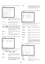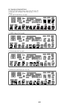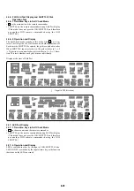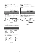
6-23
6-11. TROUBLESHOOTING
6-11-1. Cannot Enter Test Mode
You cannot enter the Test mode when either button has been pressed
by any reason with the board assembled in the front panel. In this
state, the power does not turn on even under normal condition (the
unit is kept in standby state), and also no button is active and the
remote commander is not accepted. In this case, disconnect the
MB-107 board with the SELF CHECK (pin
0
) of IF CON (IC106)
on the FR-189 board kept in low state, supply AC, and the IF CON
self-diagnosis mode will be forcibly activated. The IF CON (IC106)
checks the SELF CHECK port only after the power on reset (only
at AC supply, not in standby state). If any button is pressed, its
name is displayed on the fluorescent display tube. But, if other
than “NOTHING” is displayed though no button is pressed, it
means that any button has been pressed.
6-11-2.
Faults in Test Mode (MB-107 board)
1. The test mode menu is not displayed.
1-1. Board visual check
Check that the ICs of SYSCON (IC104), ROM (IC106 or
IC107), AVD (IC403), ARP & SERVO (IC301) are working
correctly.
Check that outside appearance of the ICs is normal.
Check that IC pins are not short-circuited.
Check that there is no soldering error.
Check that outside appearance of the capacitors and resistors
is normal.
1-2. Power supply voltage check
Check the power voltage of the power connector (CN101).
Check the power voltage of SYSCON (IC104).
Check the power voltage of ROM (IC106 or IC107).
Check the power voltage of AVD (IC403).
Check the power voltage of ARP & SERVO (IC301).
If the power voltage has any abnormality
t
Check that the power supply lines are not shorted.
Check that there is no soldering error.
If any abnormality cannot be found still
t
Check that each IC is working normally.
1-3. Clock signal check
Measure the clock signal frequency at CPUCK (CL102) of
SYSCON (IC104) with an oscilloscope.
If the 8.25 MHz signal appears.
t
Check the machine ac-
cording to section 1-3-1
If the 33 MHz signal appears.
t
Check the machine accord-
ing to section 1-3-2.
If other frequencies are output.
R106 and R107 have defective soldering, X101 crystal os-
cillator is defective.
If the measurement point is fixed to either “H” or “L”.
t
Observe XFRRST (pin-
uh
) of SYSCON (IC104) with an
oscilloscope.
If the measurement point is “L”, check the following items.
If the IC has defective soldering, if the IC is short-circuited.
If the measurement point is “H”,
t
Component X101 or SYSCON (IC104) is defective.
1-3-1. When the 8.25 MHz signal appears at CPUCK
• Check the XRD, XWRH and CS0X signal.
Observe XRD (pin-
u;
), XWRH (pin-
ua
), and CS0X (pin-
tk
)
of SYSCON (IC104) with an oscilloscope.
If these pins are fixed to either “L” (0V) or “H” (3.3V), or if
these pins stay in the center voltage, check the followings.
Check if the signal line does not have the defective solder-
ing.
Check if the signal line is short-circuited with other signal
lines.
If you cannot find any problem
t
SYSCON (IC104) is
defective.
• HA [0 to 21] signal and HD [0 to 15] signal check
Observe HA [0 to 21] (pins-
<z/x
to
<z/.
,
<zzz
to
<zz,
,
<zx/
,
1
to
5
)
of SYSCON (IC104) and HD [0 to 15] (pins-
ig
to
<z//
) with
an oscilloscope.
If these pins are fixed to either “L” (0V) or “H” (3.3V), or if
the HA pin stays in the center voltage, check the followings.
(HD stays in the center voltage when it is normal.)
t
Check if the signal line does not have the defective
soldering, or is short-circuited with other signal line or
SYSCON (IC104) is defective.
• Reset signal check
Check if XFRRST (pin-
uh
) of SYSCON (IC104) normal or
not.
The signal starts up at the same time as Vcc
t
Defective
soldering.
If the trouble does not apply to any of the above-described phe-
nomenon, SYSCON (IC104) or ROM (IC106 or IC107) is defec-
tive.


