background image

9

D

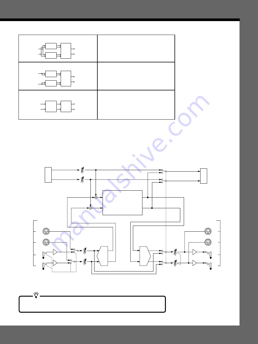
Einstellen der Eingangs- und Ausgangspegel

Das folgende Diagramm zeigt den Signalfluß von den Eingängen bis zu den Ausgängen des
Geräts mit allen Baugruppen, die für den Benutzer relevant sind.

BYPASS LINE (DIGITAL)

BYPASS SW

DIGITAL INPUT ATTENUATION  LEVEL

DIGITAL

IN

DIGITAL

OUT

CH1

CH2

ANALOG OUTPUT

CH1

CH2

CH1

CH2

BALANCED

UNBALANCED

LEVEL SW

(-20/+4 dB)

BYPASS SW

CH1

CH2

D/A

A/D

CH1

CH2

CH1

CH2

BALANCED

UNBALANCED

INPUT LEVEL

(PANEL)

ANALOG INPUT

LEVEL SW

(-20/+4 dB)

BYPASS LINE (ANALOG)

EQ BLOCK

EFFECT BLOCK

MIXER BLOCK

INPUT SW (AUTO)

OUTPUT LEVEL

(PANEL)

CH1

CH2

Wenn Sie alle Effekte ausschalten, können Sie den Effektprozessor auch als A/
D- oder D/A-Wandler verwenden.

BLOCK

A

BLOCK

B

MIX

BLOCK

IN

ch 1

ch 2

OUT

ch 1

ch 2

   PARALLEL  (PARA)

   DUAL  (DUAL)

   MORPHING  (MORPH)

BLOCK

A

BLOCK

B

MIX

BLOCK

IN

ch 1

ch 2

OUT

ch 1

ch 2

BLOCK

A

MIX

BLOCK

IN

ch 1

ch 2

OUT

ch 1

ch 2

Diese Struktur ermöglicht eine getrennte
Effektaufbereitung (beispielsweise mit Flanger und
Reverb), wobei die Signale vor der Ausgabe
gemischt werden. Im diesem Fall beeinflußt der
Flanger-Effekt den Reverb-Effekt nicht.

Bei dieser Struktur sind die Kanäle 1 und 2
voneinander getrennt. Wird beispielsweise an Kanal
1 eine Gitarre und an Kanal 2 eine Drum
angeschlossen, so läßt sich die Gitarre mit einem
Flanger-Effekt und die Drum mit einem Reverb-
Effekt aufbereiten.

Diese Struktur ermöglicht einen weichen Übergang
zwischen den in den Speicherbanken gespeicherten
Effekten: Beim Übergang von einem Effekt zu
einem anderen Effekt wird verhindert, daß der eine
Effekt plötzlich aussetzt. Siehe hierzu auch unter
„Morphing“ auf Seite 16.

Содержание DPS-V77

Страница 1: ...3 798 760 13 1 1995 by Sony Corporation Multi Effect Processor Operating Instructions Mode d emploi Bedienungsanleitung EN F D DPS V77 ...

Страница 2: ...ur plug proceed as follows The wire which is coloured blue must be connected to the terminal which is marked with the letter N or coloured black The wire which is coloured brown must be connected to the terminal which is marked with the letter L or coloured red Do not connect either wire to the earth terminal in the plug which is marked by the letter E or by the safety earth symbol Y or coloured g...

Страница 3: ...Cover MIDI Implementation Chart Back Cover Table of Contents On repacking Do not throw away the carton and the packing material This makes an ideal container when transporting the unit When shipping the unit repack it as it was packed at the factory On requesting repairs When requesting a repair data in the USER memory may be reverted to the original factory data settings Be sure to save any impor...

Страница 4: ... is also room for you to store up to 198 of your own original effects USER memory We ve also made it easy to organize the memory so you can recall effects you need without hassle Full MIDI compatibility You can use MIDI controls like wheels and velocity effect controllers to adjust effect parameters in real time RTC The MIDI interface also lets you conduct program change and data save operations S...

Страница 5: ...e REL release time Att 1 CH 1 digital input attenuator Mode analog digital both ChSel channel select Hour MIN minute Year Month Day Copy Move Exchange Delete Protect MEM memory number select EXEC execute EXEC execute MEM 1 MEM 2 EXEC execute SOURC source select DEST destination select EXEC execute SOURC source select DEST destination select MEM memory number select EXEC execute Dry on off Mode PGM...

Страница 6: ...ess the system menus and customize the effector s operating environment pages 24 and 25 1 2 3 4 5 6 7 8 9 10 10 11 12 13 14 15 17 16 10 Operation dial Shuttle ring Use to select memory numbers from the currently selected memory bank and make adjustments to parameter settings The operation dial lets you advance in one step increments The jog dial lets you advance rapidly in larger increments The ra...

Страница 7: ... to make digital connections between the effector and other components pages 8 12 13 and 29 6 BALANCED OUTPUT jacks Balanced output jacks for channel 1 and channel 2 pages 9 and 10 7 STANDARD OUTPUT jacks Standard output jacks for channel 1 and channel 2 pages 9 and 10 8 STANDARD INPUT jacks Standard input jacks for channel 1 and channel 2 pages 9 and 10 9 BALANCED INPUT jacks Balanced input jacks...

Страница 8: ... s also necessary to determine the positions of the larger blocks BLOCK A and BLOCK B Their positioning the way they are connected is called the structure Set the structure according to the kind of sound you want to make The structure screen not only lets you choose the structure type see the following chart but also lets you adjust the output level for each block represented in the chart by the M...

Страница 9: ...A converter by turning off all the effects BLOCK A BLOCK B MIX BLOCK IN ch 1 ch 2 OUT ch 1 ch 2 PARALLEL PARA DUAL DUAL MORPHING MORPH This structure lets you apply effects like flanger and reverb separately and then mix them before output In this case there s no undulation from the flanger in the reverb This structure lets you isolate ch 1 and ch 2 For example you can connect a guitar to ch 1 and...

Страница 10: ...oom is left before the INPUT signal reaches the clip point If the input signal exceeds the clip point 0 dB clip noise breaks out This unit s effect processor incorporates a 12 dB leeway Therefore even if you raise the signal level to 12 dB with the EQ block for example the internal processor will not clip the signal It is necessary however to reduce levels over 0 dB before they are output To adjus...

Страница 11: ...is should not be output from this unit only the sound of the effects should be output see Cutting the Direct Sound Dry On Off on page 25 In this situation however using bypass only cuts the sound of the effects and the sound input into the effector goes back to the mixer producing a double signal Using mute prevents the sound input into the effector from returning to the mixer and insures that onl...

Страница 12: ... 1 Hooking up to an instrument Basic Hookups Electric Guitar Guitar Pre Amplifier IN DPS V77 OUT Power Amplifier Speaker Speaker MIDI IN MIDI Foot Controller HR RC5 etc Speaker Speaker Power Amplifier DPS V77 IN MIDI IN OUT Key Board Example 2 Hooking up to a mixer cutting the direct sound When using the effector in a send return loop We recommend setting the direct output level to minus infinity ...

Страница 13: ...naural 2 MONO 2 These setting can also be made when using the analog inputs 6 Press FUNCTION C Att 1 or D Att 2 and use the operation dial to adjust the digital input levels Att 1 lets you adjust the digital input level for CH 1 Att 2 lets you adjust the digital input level for CH 2 Press FUNCTION C or D twice to link the parameters and adjust both digital input levels at the same time See pages 9...

Страница 14: ... set too high Be sure to set the input level correctly since it has a direct relationship to the quality of the effects see page 10 for details 3 Press BANK to select the memory bank containing the effect you want PRESET USER 1 or 2 PRESET banks 1 and 2 hold preset effects USER banks 1 and 2 are for user memory Choosing an Effect b Before you turn on the connected components Be sure to turn the vo...

Страница 15: ...Set Up 3 Press FUNCTION C to choose Bypass BYPASS 4 Use the operation dial to select BYPAS or Mute Press EXIT a few times to return to the PLAY screen System Bypass Mode BYPAS Mode select BYPAS Mute when you want to output the original signal without adding any effects Only the original signal is output see Bypass and Mute on page 11 you want to completely cut the sound output from the effector in...

Страница 16: ...CTION E to select Morph 3 Press FUNCTION A Time and use the operation dial to set the morphing time The morphing time is the length of time from the beginning to the end of the morphing process The effector will not respond to any commands including MIDI during this period 4 Press FUNCTION B Curve to select the morphing curve Provides a gradual transition to the next sound Brings the next sound in...

Страница 17: ...page backwards 3 Use the FUNCTION buttons A F to choose the block you want to change The screen for the chosen block appears in the display For example pressing FUNCTION A selects EQ A and the EDIT EQ A screen appears the example below shows a shelving equalizer 4 Use the FUNCTION buttons A F to select the parameter you want to change Multi display Operation dial EXIT PAGE EDIT FUNCTION A F Number...

Страница 18: ...button for the parameter you want to change twice The characters for the other channel s parameter also reverse and you can adjust both parameters at the same time Tapping in a parameter setting Tap Tempo Certain parameters like Delay Time can be set by tapping on the ENTER button After choosing the parameter you want to set press the ENTER button repeatedly to tap in the tempo you desire The proc...

Страница 19: ...ck B structure SERI 1 serial 1 FX A m FX B SERI 2 serial 2 FX B m FX A PARA parallel FX A FX B DUAL dual FX A ch 1 FX B ch 2 MORPH morphing FX A m next memory EDIT SELECT E Mixer A B C D E F FX PAGE 1 2 A A Q E B Q B FX EDIT Mixer SERI1 A B C D E F FX A Dry CH1 STRCT CH2 FX B Structure 6 0 INF INF DRY A 6 0 6 0 B 6 0 Changing the Structure The effector contains two main effect blocks which perform...

Страница 20: ...low 1 Choose an effect from the memory banks The parameters available for direct editing Active Parameters appear directly above their corresponding FUNCTION button 2 Press the FUNCTION button A F of the parameter you want to adjust To adjust parameters not displayed in the PLAY screen see Changing Effect Parameters on page 17 3 Use the operation dial or shuttle ring to adjust the parameter When c...

Страница 21: ...adjust control change number 8 balance control from 0 to 127 Setting the Real Time Control RTC By using MIDI controls such as dampers and modulation wheels you can control various characteristics of an effect in real time Since control conditions vary for each type of effect control assignments are made separately for each effect block parameter in the RTC block The effector is provided with 6 MID...

Страница 22: ...ti display Bank indicators Operation dial Memory number display BANK COMPARE SAVE Fat Reverb U1 MEM Name 8 BANK EXEC Fat Reverb MAR 22 95 00 00 SAVE Fat Reverb U1 A B C D E F MEM Name 8 BANK EXEC Fat Reverb MAR 22 95 00 00 SAVE Fat Reverb U2 A B C D E F Name 8 BANK EXEC Fat Reverb MAR 22 95 00 00 MEM SAVE Fat Reverb Fat Reverb DEL INS CLR EXEC AB ab Use the Operation dial shuttle ring Number butto...

Страница 23: ...choose PROTECT The operation dial or shuttle ring selects the memory number FUNCTION F turns protection on or off Organizing USER Memory Since each of the USER memory banks can hold up to 99 effects you may find it difficult to keep track of where certain effects are located The following procedures show you how to copy move swap and erase effects in the user memory so that you can organize the ef...

Страница 24: ...tting the Display Mode The display function lets you adjust the display mode and display contrast 1 Press SYSTEM 2 Press FUNCTION A Set Up 3 Press FUNCTION D DISP FUNCTION A Mode selects the display mode Name displays the name of the memory file in large characters and the Active Parameter settings in small characters Value displays the memory name in small characters and the Active Parameter sett...

Страница 25: ...ed by the value stored in the mixer block of each effect Setting up the Pedal Parameters Pedals connected to the PEDAL 1 and or PEDAL 2 jacks on the rear panel can be used to control the functions listed below 1 Press SYSTEM 2 Press FUNCTION C Pedal 3 Press FUNCTION A or B to choose Pedal 1 or Pedal 2 FUNCTION A Type sets the type of pedal function MEM MEM changes memory numbers up down Bank Bank ...

Страница 26: ...you decide how this unit will receive MIDI data 1 Press SYSTEM 2 Press FUNCTION D to choose MIDI 3 Press FUNCTION C to choose Rx Sw FUNCTION A EXCLV turns exclusive reception ON OFF FUNCTION B P Chg turns program change reception ON OFF FUNCTION C C Chg turns control change reception ON OFF FUNCTION D CH PR turns channel pressure reception ON OFF FUNCTION E BENDR turns pitch bender reception ON OF...

Страница 27: ...x Bulk Tx lets you transmit MIDI data in bulk 1 Press SYSTEM 2 Press FUNCTION D to choose MIDI 3 Press FUNCTION E to choose Bulk Tx FUNCTION A Type selects the type of data that will be transmitted U1 U2 U1 U2 SYSTEM or ALL FUNCTION B NUM selects whether to transmit all the contents of a memory bank or only individual memory numbers when you select U1 or U2 for the Type FUNCTION F EXEC to sends th...

Страница 28: ...s BYPASS to cancel bypass Is the effect set to OFF The morphing effect does not work Make sure to SAVE the effect after changing the structure to MORPH Make sure the structures of all the effects you want to morph between are set to MORPH The input level CLIP indicator lights Turn INPUT to the left to reduce the input level Reduce the output level of the source component Set the INPUT level select...

Страница 29: ...8 kHz internal clock ANALOG IN fs determined by connected equipment external clock DIGITAL IN fs 48 kHz internal clock ANALOG IN fs determined by connected equipment external clock DIGITAL IN ANALOG IN fs 48 kHz internal clock ANALOG IN Input Connections ANALOG and DIGITAL DIGITAL and ANALOG ANALOG only ANALOG and DIGITAL ANALOG only System Input DIGTL ChSel Att 1 Att 2 EMPHA STREO Auto 12 0 12 0 ...

Страница 30: ...Analog Output 0 dBs 0 775 Vrms XLR 3 32 connectors 1 GND 2 HOT 3 COLD Digital Input Output Pedal Input MIDI Input Output Frequency Response Signal to Noise Ratio Dynamic Range Distortion Memory Power Source Power Consumption Dimensions Mass Design and specifications subject to change without notice Jack type XLR 3 32 PHONE circuit type balanced unbalanced load impedance 600 ohms or more 10 kilohms...

Страница 31: ...31EN ...

Страница 32: ... poussière et les chocs Ne posez rien qui pourrai boucher les orifices de ventilation prévus sur le dessus du coffret et provoquer par là des défaillances Nettoyage du coffret Nettoyez le coffret les panneaux et les commandes avec un linge doux légèrement trempé dans une solution de détergent doux N utilisez aucun détergent abrasif poudre décapante ou solvant tel que de l alcool ou de la benzine R...

Страница 33: ... mémoire Utilisateur USER 23 Organisation de la mémoire Utilisateur USER 23 Réglage de l environnement du système Réglage de l horloge Clock 24 Réglage du mode d affichage 24 Réglage de la porte de bruit Gate 25 Coupure de son direct Dry On Off 25 Réglage des paramètres de pédale 25 Autres réglages 25 Utilisation MIDI Préparation d une implantation MIDI de base Basic 26 Implantation de Tableau de ...

Страница 34: ...r stocker 198 effets originaux mémoire USER de votre propre crû L organisation de la mémoire a été rendue facile de manière à ne pas avoir de complication lors du rappel des effets Totale compatibilité MIDI Vous pouvez utiliser les commandes MIDI telles que les molettes et autres contrôleurs d effet de vélocité pour ajuster les paramètres d effet en temps réel RTC L interface MIDI vous permet auss...

Страница 35: ...ute REL release time Att 1 CH 1 digital input attenuator Mode analog digital both ChSel channel select Hour MIN minute Year Month Day Copy Move Exchange Delete Protect MEM memory number select EXEC execute EXEC execute MEM 1 MEM 2 EXEC execute SOURC source select DEST destination select EXEC execute SOURC source select DEST destination select MEM memory number select EXEC execute Dry on off Mode P...

Страница 36: ... Utilisez cette touche pour accéder aux menus de système et pour personnaliser l environnement d exploitation de l effecteur pages 24 et 25 10 Bague d exploitation Bague navette Utilisez pour sélectionner les numéros mémorisés sur le bloc de mémoire actuellement sélectionné et apporter des ajustements aux réglages de paramètre La bague d exploitation autorise une avance par palier d un cran tandis...

Страница 37: ... pour effectuer les connexions numériques entre l effecteur et d autres composants pages 8 12 13 et 29 6 Jacks de sortie symétrique BALANCED OUTPUT Prises de sortie symétrique pour le canal 1 Ch 1 et le canal 2 Ch 2 pages 9 et 10 7 Jacks de sortie standard STANDARD OUTPUT Prises de sortie standard pour le canal 1 et le canal 2 pages 9 et 10 8 Jacks d entrée standard STANDARD INPUT Prises d entrée ...

Страница 38: ...nt de l égaliseur ou si vous égalisez le son produit par l effet EQ BLOCK EQ BLOCK BLOCK B BLOCK A FX BLOCK réverb changeur de hauteur choeur etc FX BLOCK réverb changeur de hauteur choeur etc FX BLOCK EQ BLOCK EQ BLOCK FX BLOCK Si on choisit Pre Si on choisit Post Par exemple si vous réglez le BLOCK A comme flanger intense et le BLOCK B comme la plus grande réverbération disponible cf page 17 pou...

Страница 39: ...RA DUAL DUAL MORPHING MORPH BLOCK A BLOCK B MIX BLOCK IN ch 1 ch 2 OUT ch 1 ch 2 BLOCK A MIX BLOCK IN ch 1 ch 2 OUT ch 1 ch 2 Cette structure vous permet d appliquer séparément des effets tels que flanger et réverb et de les mixer ensuite avant la sortie Dans ce cas il n y a pas d ondulation du flanger sur la réverbération Cette structure vous permet d isoler le canal 1 Ch 1 et le canal 2 Ch 2 Par...

Страница 40: ...nuellement Réglage des niveaux INPUT OUTPUT pour éviter un écrêtage Les numéros sur le décibelmètre indiquent en décibels combien il reste d espace avant que le signal INPUT n arrive à son point d écrêtage Si le signal entré dépasse ce point 0 dB un bruit d écrêtage se produira Le processeur d effet de cet appareil autorise une dérive de 12 dB Par conséquent même si vous élevez le niveau du signal...

Страница 41: ...fets Par conséquent aucun son ne provient de l appareil Le réglage de la touche BYPASS comme Sourdine ou Découplage s accomplit sur le menu SYSTEM Démarrage Une mise en sourdine du son n est pas seulement une réduction du volume à 0 Elle permet plutôt d éviter un retour du son vers le mixeur quand l appareil est raccordé dans une boucle envoi retour avec un mixeur Idéalement quand cet appareil est...

Страница 42: ...n de cet appareil et de tous les composants à raccorder tels que claviers et haut parleurs actifs haut parleurs à ampli incorporé Une fois qu elles sont terminées vérifiez à nouveau toutes les connexions avant de rebrancher le cordon d alimentation dans la prise du secteur Si les composants raccordés fournissent des signaux qui pourraient provoquer une distorsion ajustez le bouton INPUT de cet app...

Страница 43: ...A B C D E F M System Setup Input Bypass Gate DISP A B C D E F Clock Dry off FX System Digital I O DIGTL A B C D E F ChSel Att 1 Att 2 EMPHA STREO Auto 12 0 12 0 Mode Input Mode 5 Appuyez sur FUNCTION B ChSel et servez vous de la bague d exploitation pour sélectionner le s canal canaux d entrée Pour utiliser les deux CH1 et CH2 sélectionnez Stéréo STREO Pour utiliser seulement CH1 sélectionnez Mona...

Страница 44: ... CEQ Hall CEQ Hall Fat Reverb RotHI Size Size FxB 1 RotHI FxA 1 1 0 0 64 0 8 0 70 6 0 6 0 Paramètres actifs cf page 20 Nom de mémoire Icône de catégorie Message de structure cf page 19 CH 2 CH 1 CLIP 6 12 18 24 30 36 dB CH 1 CH 2 Les voyants du haut et du bas s allument pour le bloc PRESET ou USER 2 Seul le voyant du bas s allume pour le bloc PRESET ou USER 1 2 1 PRESET USER 2 1 PRESET USER 4 Séle...

Страница 45: ... E F Clock Dry off FX Sortie sans effets BYPASS MUTE L effecteur possède deux modes de découplage différents Bypass découplage et Mute sourdine Par conséquent selon le mode de découplage choisi vous pourrez utiliser la touche BYPASS pour couper la sortie du son original ou pour fournir le son original sans effets Une fois que le mode BYPASS est réglé il suffit d appuyer sur BYPASS pour actualiser ...

Страница 46: ...ON E pour sélectionner Morph Sélection d un effet System Set UP Memry Pedal M I D I Morph A B C D E F M System Morphing Condition 2 0 A B C D E F Curve Time System Morphing Condition 2 0 A B C D E F Time Curve 3 Appuyez sur FUNCTION A Time et servez vous de la bague d exploitation pour définir la durée de morphage La durée de morphage est le temps compris entre le début et la fin du processus de m...

Страница 47: ...ets stockés dans les blocs de mémoire préréglée L effecteur dispose de 198 effets différents dans sa mémoire préréglée et d une capacité de mémorisation de 198 autres effets créés par l utilisateur en altérant les valeurs des paramètres Multi affichage Bague navette Touches numériques Bague d exploitation Continuer page suivante 3 Utilisez les touches FUNCTION A F pour choisir le bloc que vous dés...

Страница 48: ...ique Pour changer simultanément le même paramètre pour CH 1 et CH 2 LINK Appuyez deux fois sur la touche FUNCTION pour le paramètre que vous voulez changer Les caractères pour le paramètre de l autre canal s inversent aussi et vous pouvez alors ajuster les deux paramètres en même temps Réglage d un paramètre par poussées sur la touche ENTER tempo de poussée Certains paramètres comme le temps de re...

Страница 49: ...D E F Dry STRCT FX B Fx A dB INF INF A 6 0 6 0 B FX A CH1 CH2 6 0 6 0 DRY 4 Utilisez la touche FUNCTION B ou C pour sélectionner le bloc d effet contenant les réglages de paramètre à copier 5 Appuyez sur FUNCTION F EXEC pour copier les réglages de paramètre du bloc d effet sélectionné à l étape 4 Pour copier un effet entier cf page 23 PLAY CEQ Hall CEQ Hall Fat Reverb RotHI Size Size FxB 1 RotHI F...

Страница 50: ... blocs de mémoire Les paramètres disponibles pour l édition directe Paramètres Actifs apparaissent directement au dessus de la touche FUNCTION correspondante 2 Appuyez sur la touche FUNCTION A F du paramètre que vous voulez ajuster Pour ajuster des paramètres non affichés sur l écran PLAY cf Changement des paramètres d effet en page 17 3 Servez vous de la bague d exploitation ou de la bague navett...

Страница 51: ...alance d effet de 75 25 à 25 75 quand vous ajustez le changement de contrôle Numéro 8 contrôle de balance de 0 à 127 Réglage du contrôle en temps réel RTC En faisant appel aux commandes MIDI telles que les molettes d amortissement et de modulation vous pourrez contrôler diverses caractéristiques d un effet en temps réel Etant donné que les conditions du contrôle varient pour chaque type d effet le...

Страница 52: ... La procédure suivante montre comment stocker un effet dans un des blocs de mémoire Utilisateur USER SAVE Fat Reverb U1 A B C D E F MEM Name 8 BANK EXEC Fat Reverb MAR 22 95 00 00 SAVE Fat Reverb U2 A B C D E F Name 8 BANK EXEC Fat Reverb MAR 22 95 00 00 MEM Bague d exploitation Touches numériques SAVE Bague navette Affiche de numéro en mémoire Voyants de bloc de mémoire Multi affichage SAVE Fat R...

Страница 53: ...3 Appuyez sur FUNCTION A pour choisir Copy FUNCTION A SOURC choisit le numéro de mémoire de source à copier FUNCTION B DEST choisit la destination FUNCTION F EXEC exécute l opération de copie Déplacement en mémoire USER Move Cette fonction vous permet de déplacer le contenu d un numéro spécifié de la mémoire USER vers un autre numéro de la mémoire USER 1 Appuyez sur SYSTEM 2 Appuyez sur FUNCTION B...

Страница 54: ...ge de l horloge Clock La fonction Clock permet d ajuster l heure et la date sur l horloge incorporé à l effecteur Une fois que l horloge est réglée la date et l heure sont automatiquement conservées dans la mémoire Utilisateur où sont sauvegardés les effets traités 1 Appuyez sur SYSTEM 2 Appuyez sur FUNCTION A Set Up 3 Appuyez sur FUNCTION E Clock FUNCTION A Month règle le mois FUNCTION B Day règl...

Страница 55: ... de chaque effet Réglage des paramètres de pédale Les pédales raccordées aux jacks PEDAL 1 et ou PEDAL 2 sur le panneau arrière peuvent servir pour contrôler les fonctions reprises ci après 1 Appuyez sur SYSTEM 2 Appuyez sur FUNCTION C Pedal 3 Appuyez sur FUNCTION A ou B pour choisir Pedal 1 ou Pedal 2 FUNCTION A Type définit le type de fonction de pédale MEM MEM change les numéros de mémoire vers...

Страница 56: ...HIFT en combinaison avec 4 ou pour apporter les changements souhaités Sélectionnez Basic Table Rx SW Tx SW Bulk Tx afin de régler les fonctions MIDI de base déterminer le tableau de commande MIDI déterminer comment les données MIDI seront reçues déterminer comment les données MIDI seront transmises transmettre les données MIDI en bloc Préparation d une implantation MIDI de base Basic Servez vous d...

Страница 57: ... Appuyez sur FUNCTION D pour choisir MIDI 3 Appuyez sur FUNCTION D pour choisir Tx Sw FUNCTION A PANEL sélectionne si les messages exclusifs qui apparaissent quand sont actionnées les touches du panneau avant seront transmis ou non via MIDI OUT Transmission des données MIDI en bloc Bulk Tx Bulk Tx vous permet de transmettre les données MIDI en bloc 1 Appuyez sur SYSTEM 2 Appuyez sur FUNCTION D pou...

Страница 58: ...TPUT CH1 CH2 CH1 CH2 BALANCED UNBALANCED LEVEL SW 20 4 dB BYPASS SW CH1 CH2 D A A D CH1 CH2 CH1 CH2 BALANCED UNBALANCED INPUT LEVEL PANEL ANALOG INPUT LEVEL SW 20 4 dB BYPASS LINE ANALOG DSP DIGITAL IN OUT MIDI IN MIDI OUT THRU CPU PEDAL IN 1 PEDAL IN 2 CLOCK PRESET MEMORY LCD SW LED METER JOG SHUTTLE USER MEMORY INPUT SW AUTO OUTPUT LEVEL PANEL CH1 CH2 Le son n est pas modifié par l effet sélecti...

Страница 59: ...ENTREE ACTIVES fs 48 kHz horloge interne ANALOG IN fs déterminé par équipement raccordé horloge externe DIGITAL IN fs 48 kHz horloge interne ANALOG IN fs déterminé par équipement raccordé horloge externe DIGITAL IN ANALOG IN fs 48 kHz horloge interne ANALOG IN Connexions d entrée ANALOG et DIGITAL DIGITAL et ANALOG ANALOG seul ANALOG et DIGITAL ANALOG seul Tableau de borne E S numérique Type AES E...

Страница 60: ...originales définies en usine 1 Mettez l appareil hors tension 2 Enfoncez SAVE et ENTER et remettez l appareil sous tension Le message Initialized apparaît sur l affichage et l appareil revient à ses réglages d origine Remarque Toutes les données de la mémoire Utilisateur sont remplacées par les données originales d usine Avant de procéder à cette réinitialisation prenez soin de sauvegarder toutes ...

Страница 61: ...31F ...

Страница 62: ...tem Sonnenlicht starker Staubentwicklung oder mechanischen Stößen ausgesetzt sind Stellen Sie nichts oben auf das Gehäuse da es sonst durch Blockieren der Ventilationsöffnungen zu Fehlfunktionen kommen kann Zur Reinigung des Gehäuses Reinigen Sie das Gehäuse das Bedienungspult und die Bedienungselemente mit einem weichen leicht mit mildem Haushaltsreiniger angefeuchteten Tuch Scheuerschwämme Scheu...

Страница 63: ... Schutz der USER Speicherung 23 USER Speicherverwaltung 23 Zusätzliche Systemeinstellungen Einstellen der Uhr Clock 24 Konfigurieren der Anzeige DISP 24 Einstellen der Noise Gate Funktion Gate 25 Abschalten des Direktsignals Dry On Off 25 Einstellen der Pedalparameter 25 Sonstige Einstellungen 25 MIDI Betrieb Einstellen der MIDI Grundfunktionen Basic 26 Einstellen der MIDI Programmtabelle Table 26...

Страница 64: ... USER Speicher für 198 selbst kreierte Effekte Trotz der vielen Speichermöglichkeiten leidet die Übersicht nicht jeder Effekt kann jederzeit problemlos abgerufen werden Voll MIDI kompatibel Mit den MIDI Steuerfunktionen wie Wheels und Velocity Effekt lassen sich die Effektparameter in Echtzeit RTC Real Time Control einstellen Und über die MIDI Schnittstelle können Sie Programmänderungen und Datens...

Страница 65: ... REL release time Att 1 CH 1 digital input attenuator Mode analog digital both ChSel channel select Hour MIN minute Year Month Day Copy Move Exchange Delete Protect MEM memory number select EXEC execute EXEC execute MEM 1 MEM 2 EXEC execute SOURC source select DEST destination select EXEC execute SOURC source select DEST destination select MEM memory number select EXEC execute Dry on off Mode PGM ...

Страница 66: ...en Stummschalten Mute des Effektprozessor Ausgangssignals siehe Seite 15 17 Speicherbankanzeigen Zeigt die momentan gewählte Speicherbank an PRESET 1 PRESET 2 USER 1 oder USER 2 siehe Seite 14 1 POWER ON OFF Schalter Zum Ein und Ausschalten des Geräts Beim Einschalten wird der letzte Speichereffekt abgerufen und der Wiedergabemodus automatisch aktiviert 2 INPUT Pegelregler Durch Drehen dieses Regl...

Страница 67: ...eren Geräts verbunden werden siehe Seite 8 12 13 und 29 6 BALANCED OUTPUT Buchsen Diese symmetrischen Ausgangsbuchsen geben das Signal von Kanal 1 und 2 aus siehe Seite 9 und 10 7 STANDARD OUTPUT Buchsen Diese Standard Ausgangsbuchsen geben das Signal von Kanal 1 und 2 aus siehe Seite 9 und 10 8 STANDARD INPUT Buchsen Diese Standard Eingangsbuchsen dienen zur Zuleitung des Signals von Kanal 1 und ...

Страница 68: ...OCK A EQ BLOCK EQ BLOCK Signalflußdiagramm Vorbereitung FX BLOCK Reverb Pitch Shifter Chorus usw FX BLOCK Reverb Pitch Shifter Chorus usw Bei Wahl von Pre Bei Wahl von Post FX BLOCK EQ BLOCK EQ BLOCK FX BLOCK Weiterhin kann auch die Position der Hauptblöcke BLOCK A und BLOCK B vom Benutzer festgelegt werden Die Positionierung und die Art der Zusammenschaltung wird als Struktur bezeichnet Stellen S...

Страница 69: ...IN ch 1 ch 2 OUT ch 1 ch 2 PARALLEL PARA DUAL DUAL MORPHING MORPH BLOCK A BLOCK B MIX BLOCK IN ch 1 ch 2 OUT ch 1 ch 2 BLOCK A MIX BLOCK IN ch 1 ch 2 OUT ch 1 ch 2 Diese Struktur ermöglicht eine getrennte Effektaufbereitung beispielsweise mit Flanger und Reverb wobei die Signale vor der Ausgabe gemischt werden Im diesem Fall beeinflußt der Flanger Effekt den Reverb Effekt nicht Bei dieser Struktur...

Страница 70: ...Klangbeeinträchtigungen Da der Effektprozessor des Geräts jedoch einen Spielraum von 12 dB besitzt ist eine Signalanhebung von bis zu 12 dB beispielsweise durch den EQ Block möglich ohne daß der Prozessor ein Clippen verursacht Allerdings ist es in diesem Fall erforderlich daß über 0 dB liegende Pegel vor der Signalausgabe reduziert werden Zum Einstellen des Effektpegels wählen Sie Mixer im EDIT M...

Страница 71: ...iglich den Effekt das Eingangsignal des Effektprozessors wird jedoch zum Mischer zurückgesendet und es entsteht ein doppeltes Signal Die Mute Funktion hingegen verhindert daß das Eingangssignal des Effektprozessors zum Mischer zurückgelangt der Mischer erhält nur das Originalsignal Gitarre Keyboard usw Die Mute Funktion ist in diesem Fall also keine Pegel Stummschaltung sondern eine Effekt Stummsc...

Страница 72: ...lle anderen Komponenten wie Keyboard Aktiv Lautsprecher usw aus bevor Sie Anschlüsse vornehmen Überprüfen Sie den Anschluß nochmals bevor Sie das Netzkabel an die Wandsteckdose anschließen Wenn die angeschlossenen Komponenten einen zu hohen Ausgangssignalpegel liefern so daß es zu Verzerrungen kommt reduzieren Sie entweder den Ausgangspegel am angeschlossenen Gerät oder den Eingangspegel am INPUT ...

Страница 73: ...nstellung kann auch vorgenommen werden wenn analoge Eingänge gewählt wurden 6 Drücken Sie FUNCTION C Att 1 oder D Att 2 und stellen Sie dann mit der Einstellscheibe den Pegel des digitalen Eingangssignals ein Att 1 dient zur Einstellung des digitalen Eingangssignalpegels von CH1 Att 2 dient zur Einstellung des digitalen Eingangssignalpegels von CH2 Durch zweimaliges Drücken von FUNCTION C oder D w...

Страница 74: ...ze FxB 1 RotHI FxA 1 1 0 0 64 0 8 0 70 6 0 6 0 Kategorie Ikone Speichername Aktive Parameter siehe Seite 20 Strukturanzeige siehe Seite 19 In den USER Speicherbanken 1 und 2 können vom Benutzer selbst erstellte Effekte gespeichert werden 4 Wählen Sie den gewünschten Effekt 1 99 Drehen Sie hierzu den Shuttlering die Einstellscheibe bis die Effektnummer angezeigt wird Wahlweise kann die Effektnummer...

Страница 75: ... I D I Morph A B C D E F M System Setup Input Bypass Gate DISP A B C D E F Clock Dry off FX 4 Wählen Sie mit der Einstellscheibe BYPAS oder Mute Drücken Sie EXIT wiederholt um in das PLAY Menü zurückzuschalten System Bypass Mode BYPAS Mode Umgehungsart BYPAS Mute In folgenden Fällen verwenden Zur Ausgabe des Originalsignals ohne Effekte siehe auch Bypass und Mute Funktion auf Seite 11 Zum vollstän...

Страница 76: ...ing Zeiten und Kurven einzustellen Wahl eines Effektes System Morphing Condition 2 0 A B C D E F Curve Time System Morphing Condition 2 0 A B C D E F Time Curve Morphing Wenn für zwei Effekte die Struktur MORPH gewählt ist kann weich von einem zum anderen Effekt übergeblendet werden Einzelheiten zur Systemstruktur finden Sie auf Seite 8 zum Ändern der Struktur siehe Seite 19 Hinweis Während des Mo...

Страница 77: ... SELECT Menü erscheint im Display Die ganz oben rechts stehende Ziffer gibt die Anzahl der Seiten Basismenüs des momentanen Blocks an Bei der Ziffer im schwarzen Kasten handelt es sich um die aktuelle Seite Durch erneutes Drücken von EDIT PAGE kann zur nächsten Seite geblättert werden Durch Drücken von EDIT PAGE bei gedrückt gehaltener ENTER SHIFT Taste kann zur vorausgegangenen Seite zurückgeblät...

Страница 78: ...ig dieselben Parameter von CH1 und CH2 einzustellen LINK Drücken Sie die FUNCTION Taste des zu ändernden Parameters zweimal Die Anzeige des Parameters des anderen Kanals wird dann ebenfalls hervorgehoben und beide können gleichzeitig eingestellt werden Parametereinstellung durch wiederholtes Antippen Tap Tempo Einige Parameter beispielsweise Delay Time können durch wiederholtes Antippen der ENTER ...

Страница 79: ...X A FX B DUAL FX A CH 1 FX B CH 2 MORPH Morphing FX A m nächster Speicher 5 Drücken Sie FUNCTION EXEC um den Kopiervorgang einzuleiten Die Parametereinstellungen des in Schritt 4 gewählten Effektblocks werden kopiert Zum Kopieren eines ganzen Effektes siehe Seite 23 EDIT Mixer SERI1 A B C D E F FX A Dry CH1 STRCT CH2 FX B Structure 6 0 INF INF DRY A 6 0 6 0 B 6 0 EDIT SELECT E Mixer A B C D E F FX...

Страница 80: ...n Abschnitt Wahl der aktiven Parameter 1 Wählen Sie einen Effekt aus den Speicherbanken aus Die direkt editierbaren Parameter aktive Parameter werden über den betreffenden FUNCTION Tasten angezeigt 2 Drücken Sie die FUNCTION Taste A F des einzustellenden Parameters Zum Einstellen von nicht im PLAY Menü angezeigten Parametern siehe unter Ändern von Effektparametern auf Seite 17 3 Stellen Sie den Pa...

Страница 81: ...ourc Wählt die Steuerquelle C0 C31 Legt die MIDI Steuernummer fest C64 C120 Legt die MIDI Steuernummer fest Note N Zur Verwendung einer Notennummer Note V Zur Verwendung einer Notengeschwindigkeit bei Geschwindigkeit 0 erhält man Note Off BENDR Zur Verwendung von Pitch Bender CH PR Zur Verwendung von Channel Pressure M CLK Zur Verwendung der Tempoanzeige MIDI Clock als Steuerquelle Einstellungen z...

Страница 82: ...everb MAR 22 95 00 00 MEM SAVE Fat Reverb Fat Reverb DEL INS CLR EXEC AB ab Falls erforderlich drücken Sie EXIT um zum vorausgegangenen Menü zurückzukehren 5 Drücken Sie FUNCTION F EXEC um die Sicherung auszuführen Das PLAY Menü erscheint im Display Verwendetes Bedienungselement Einstellscheibe Shuttlering Nummerntasten FUNCTION A CLR FUNCTION B DEL FUNCTION C INS FUNCTION D FUNCTION E AB ab FUNCT...

Страница 83: ...3 Drücken Sie FUNCTION A zur Wahl von Copy FUNCTION A SOURC wählt die Nummer des zu kopierenden Speichers FUNCTION B DEST wählt das Kopierziel FUNCTION F EXEC führt den Kopiervorgang aus Verschieben eines Effektes im USER Speicher Move Mit diesem Befehl kann ein Effekt von einer USER Speichernummer zu einer anderen verschoben werden 1 Drücken Sie SYSTEM 2 Drücken Sie FUNCTION B zur Wahl von MEMRY ...

Страница 84: ...nstellung in Kleinschrift angezeigt Value Der Speichername wird in Kleinbuchstaben und die Aktivparameter Einstellung in Großschrift angezeigt FUNCTION B LCD stellt den Display Kontrast ein Im system Menü können verschiedene zusätzliche Einstellungen und Konfigurierungen vorgenommen werden Durch einmaliges Drücken von EXIT kann zum vorausgegangenen Menü zurückgekehrt werden Um am Ende der Einstell...

Страница 85: ...er Pegel wird auf gesetzt PGM Der Direktsignalpegel entspricht dem für jeden Effekt im Mischerblock gespeicherten Wert Einstellen der Pedalparameter Mit den an den PEDAL 1 und oder PEDAL 2 Buchsen an der Rückseite angeschlossenen Pedalen können die unten angegebenen Funktionen gesteuert werden 1 Drücken Sie SYSTEM 2 Drücken Sie FUNCTION C Pedal 3 Drücken Sie FUNCTION A oder B zur Wahl von Pedal 1 ...

Страница 86: ...l von Table FUNCTION A MIDI wählt die MIDI Programmänderungsnummer FUNCTION B BANK wählt die Speicherbank bzw Bypass FUNCTION C MEM wählt die Speichernummer Einstellen der Empfangsart der MIDI Daten Rx Sw Mit Rx Sw wird festgelegt wie die MIDI Daten empfangen werden 1 Drücken Sie SYSTEM 2 Drücken Sie FUNCTION D zur Wahl von MIDI 3 Drücken Sie FUNCTION C zur Wahl von Rx Sw FUNCTION A EXCLV schaltet...

Страница 87: ...lk Bulk Tx Mit Bulk Tx können die MIDI Daten als Bulk gesendet werden 1 Drücken Sie SYSTEM 2 Drücken Sie FUNCTION D zur Wahl von MIDI 3 Drücken Sie FUNCTION E zur Wahl von Bulk Tx FUNCTION A Type wählt die Art der Daten die gesendet werden U1 U2 U1 U2 SYSTEM oder ALL FUNCTION B NUM wählt ob der Inhalt der ganzen Speicherbank oder einer bestimmten Speichernummer gesendet wird wenn U1 oder U2 für Ty...

Страница 88: ...durch Häufig ist die Störung lediglich auf einen Bedienungs Einstellungsfehler oder ein nicht korrekt angeschlossenes Kabel zurückzuführen Kein Ton oder zu geringer Pegel Die MUTE Funktion durch Drücken von BYPASS ausschalten Bei analogem Eingangssignal darauf achten daß der INPUT Pegelregler richtig eingestellt ist Bei digitalem Eingangssignal die Eingangspegeleinstellung im System Setup Menü übe...

Страница 89: ... Synchronisierung ANALOG IN fs von angeschlossenem Gerät bestimmt externe Synchronisierung DIGITAL IN fs 48 kHz interne Synchronisierung ANALOG IN fs von angeschlossenem Gerät bestimmt externe Synchronisierung DIGITAL IN ANALOG IN fs 48 kHz interne Synchronisierung ANALOG IN Eingangsanschluß ANALOG und DIGITAL DIGITAL und ANALOG nur ANALOG ANALOG und DIGITAL nur ANALOG System Input DIGTL ChSel Att...

Страница 90: ...n schalten Sie das Gerät wieder ein Initialized erscheint im Display und alle Einstellungen werden in die werksseitigen Ausgangszustände zurückgesetzt Hinweis Beim Rücksetzen werden die Daten des USER Speichers gelöscht Sichern Sie deshalb alle Daten zuvor beispielsweise in einem MIDI Data Filer Auswechseln der Pufferbatterie des Speichers Wenn beim Einschalten Battery Low im Display erscheint ist...

Страница 91: ...pe FX B Type PAGE 1 2 3 4 5 FUNCTION A B C D E F PAGE 1 2 3 FUNCTION A B C D E F FX A Type PAGE 1 2 3 4 5 FUNCTION A B C D E F Blank Chart Tableaux d éspace Leerdiagramm BANK No Mixer Structure Effect A Level ch1 dB ch2 dB Effect B Level ch1 dB ch2 dB Dry Level ch1 dB ch2 dB ...

Страница 92: ...mber True Voice Velocity Note ON Note OFF After Key s Touch Ch s Pitch Bend 0 31 64 120 Control Change Prog Change True System Exclusive Song Pos Common Song Sel Tune System Clock Real Time Commands Aux Local ON OFF All Notes OFF Messages Active Sense Reset Notes 1 Used as a RTC Real Time Controller input source Mode 1 OMNI ON POLY MODE 2 OMNI ON MONO YES Mode 3 OMNI OFF POLY MODE 4 OMNI OFF MONO ...

Отзывы: