


6-56
3. External Microphone Separation Check
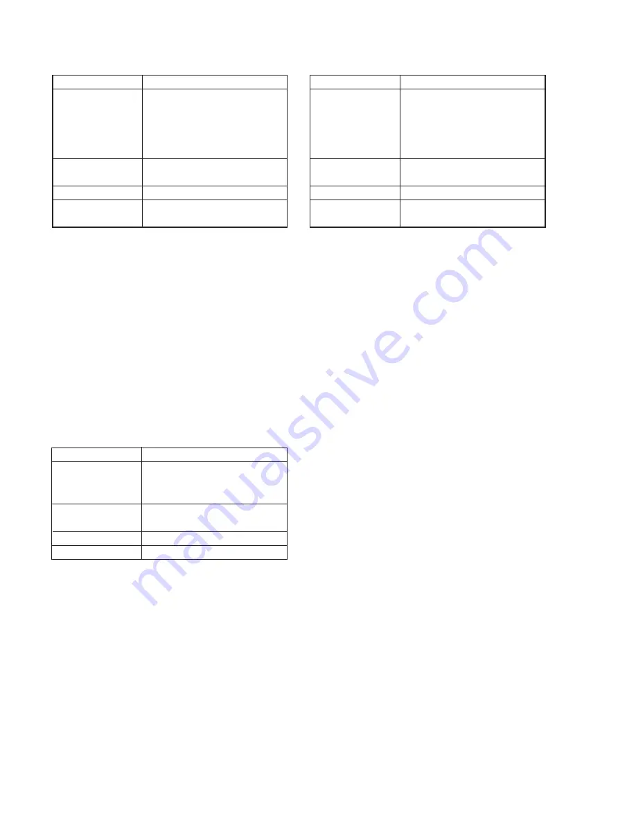
5. External Microphone Noise Level Check
Connection:
Connect the following terminals of the 26PIN multi connector using
a resistor.
1) Connect a 22 k
Ω
resistor between Pin
8
(S STATUS) and Pin
!§
(GND).
(Turn OFF SW2 of the I/O board-1 tool.)
2) Connect a 470 k
Ω
resistor between Pin
6
(S STATUS2) and Pin
!§
(GND).
(Turn ON SW3 of the I/O board-1 tool.)
Checking Method
1) Input a 1kHz, –44 dBs signal to Pin
!£
(right) of the 26PIN multi
connector.
2) Check that the signal level of the left channel of the video output
(Note 1) satisfies the specified value.
Note 1:
Impose a 47 k
Ω
resistance to the left of the vide audio/
headphone terminal, and turn the power ON from OFF.
4. External Microphone Distortion Rate Check
Mode
Signal
Measurement Point
Measuring Instrument
Specified Value
Camera mode recording
1 kHz, –44 dBs signal
Pin
!£
(right) of the 26PIN multi
connector
(Connect Pin
!
∞
(left) to Pin
!¶
(GND)
with a jumper wire.)
Audio video/headphone terminal left
(47 k
Ω
load)
Audio level meter
Below –40 dBs
(IHF-A filter ON, 20 kHz LPF ON)
Connection:
Connect the following terminals of the 26PIN multi connector using
a resistor.
1) Connect a 22 k
Ω
resistor between Pin
8
(S STATUS) and Pin
!§
(GND).
(Turn OFF SW2 of the I/O board-1 tool.)
2) Connect a 470 k
Ω
resistor between Pin
6
(S STATUS2) and Pin
!§
(GND).
(Turn ON SW3 of the I/O board-1 tool.)
Checking Method
1) Input a 1kHz, –44 dBs signal to Pins
!
∞
(left) and
!£
(right) of
the 26PIN multi connector.
2) Check that the distortion rate of the audio output (Note 1) satisfies
the specified value.
Note 1:
Impose a 47 k
Ω
resistance to the left Audio video/
headphone terminal, and turn the power ON from OFF.
Mode
Signal
Measurement Point
Measuring Instrument
Specified Value
Camera mode recording
Audio level meter
Below 0.4% (20 kHz LPF ON)
Audio video/headphone terminal left
(47 k
Ω
load)
1 kHz, –44 dBS signal
Pin
!
∞
(left) and Pin
!£
(right) of 26PIN
multi connector
Mode
Signal
Measurement Point
Measuring Instrument
Specified Value
Camera mode recording
No signal:Connect pin
!£
(right) and
Pin
!¶
(GND), and Pin
!
∞
(left) and
Pin
!¶
(GND) of the 26PIN multi
connector with jumper wires
respectively.
Audio video/headphone terminal left
(47k
Ω
load)
Audio level meter
Below –45 dBs
(IHF-A filter ON, 20 kHz LPF ON)
Connection:
Connect the following terminals of the 26PIN multi connector using
a resistor.
1) Connect a 22 k
Ω
resistor between Pin
8
(S STATUS) and Pin
!§
(GND).
(Turn OFF SW2 of the I/O board-1 tool.)
2) Connect a 470 k
Ω
resistor between Pin
6
(S STATUS2) and Pin
!§
(GND).
(Turn ON SW3 of the I/O board-1 tool.)
Checking Method
1) Check that the noise level of the audio output (Note 1) satisfies
the specified value.
Note 1:
Impose a 47 kW resistance to the left video audio/
headphone terminal, and turn the power ON from OFF.
Содержание DCR-PC7
Страница 41: ...6 2 Fig 6 1 1 J 1 J 2 J 3 J 4 J 5 J 6 J 7 J 8 J 9 J 10 J 11 ...
Страница 92: ...6 57 ...
Страница 95: ...6 60 ...
Страница 96: ...6 61 ...
Страница 97: ...6 62 ...
Страница 104: ... 282 Sony EMCS Co DCR PC7 PC7E 9 973 919 11 2006I0500 1 2006 9 Published by Kohda TEC ...


