


6-1
SECTION 6
ADJUSTMENTS
6-1. CAMERA SECTION ADJUSTMENTS
When performing adjustments, refer to the layout
diagrams for adjustment related parts beginning from
page 6-30.
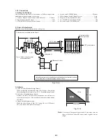
1-1.
PREPARATIONS BEFORE ADJUSTMENT
(CAMERA SECTION)
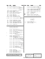
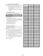
1-1-1. List of Service Tools
• Oscilloscope
• Regulated power supply
• Color monitor
• Vectorscope
• Digital voltmeter
Note:
NTSC model
: DCR-PC7
PAL model
: DCR-PC7E
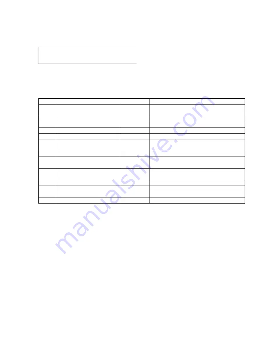
Name
Parts Code
Usage
Ref No.
J-1
J-2
J-3
J-4
J-5
J-6
J-7
J-8
J-9
J-10
J-11
Filter for color temperature correction
(C14)
ND filter 1.0
ND filter 0.3
Pattern box PTB-450
Color chart for pattern box
Adjusting remote commander
(RM-95-remodeled partly)
Note 1
Siemens star
CPC-6 jig
CPC-6 terminal board jig
I/O board -1 jig
Extension cable (18P, 0.5 mm)
Clear chart for pattern box
J-6080-058-A
J-6080-808-A
J-6080-818-A
J-6082-200-A
J-6020-250-A
J-6082-053-B
J-6080-875-A
J-6082-370-A
J-6082-371-A
J-6082-372-A
J-6082-374-A
J-6080-621-A
Auto white balance adjustment/check
White balance adjustment/check
White balance check
White balance check
For checking the flange back
For adjusting the video section
For adjusting the viewfinder
For adjusting the video section
For adjusting the viewfinder
For connecting the adjusting remote commander
For extension between the MR-36 board (CN3100) and the
capstan motor.
Note 1:
If the micro processor IC in the adjusting remote commander is not the new micro processor (UPD7503G-C56-12), the pages cannot
be switched. In this case, replace with the new micro processor (8-759-148-35).
DCR-PC7/PC7E
Содержание DCR-PC7
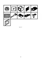
Страница 41: ...6 2 Fig 6 1 1 J 1 J 2 J 3 J 4 J 5 J 6 J 7 J 8 J 9 J 10 J 11 ...
Страница 92: ...6 57 ...
Страница 95: ...6 60 ...
Страница 96: ...6 61 ...
Страница 97: ...6 62 ...
Страница 104: ... 282 Sony EMCS Co DCR PC7 PC7E 9 973 919 11 2006I0500 1 2006 9 Published by Kohda TEC ...


