background image

6-1

Ref. No.

Part No.

Description

Remark

Ref. No.

Part No.

Description

Remark

SECTION  6

REPAIR  PARTS  LIST

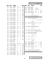
6-1-1. UPPER  CABINET  SECTION

NOTE:

• -XX and -X mean standardized parts, so they may

have some difference from the original one.

• Color Indication of Appearance Parts

Example:
KNOB, BALANCE (WHITE) . . . (RED)

Parts Color

Cabinet's Color

• Items marked “*” are not stocked since they are

seldom required for routine service. Some delay
should be anticipated when ordering these items.

• The mechanical parts with no reference number in

the exploded views are not supplied.

• Accessories are given in the last of the electrical

parts list.

6-1. EXPLODED  VIEWS

The components identified by mark

0

 or dotted line with mark 

0

 are

critical for safety.
Replace only with part number speci-
fied.

Les composants identifiés par une
marque 

0

 sont critiquens pour la

sécurité.
Ne les remplacer que par une pièce
portant le numéro spécifié.

DSC-P1

1

X-3951-025-1 CABINET (FRONT) ASSY

2

3-989-735-81 SCREW (M1.7), LOCK ACE, P2

3

3-064-242-01 CABINET (BOTTOM)

4

3-969-387-01 FOOT, RUBBER

*

5

3-064-227-01 SHEET, MICROPHONE

*

6

3-065-229-01 SHEET (UPPER)

7

3-989-735-51 SCREW (M1.7), LOCK ACE, P2

8

A-7096-377-A PW-122 BLOCK ASSY

*

9

3-055-971-01 CUSHION, MICROPHONE

10

3-318-382-03 SCREW (1.7), TAPPING

11

X-3951-027-1 CABINET (UPPER) ASSY

12

3-064-263-01 BUTTON, SHUTTER

13

3-064-260-01 KNOB, POWER

14

3-064-237-01 SPRING, COMPRESSION

15

3-064-266-01 SLIDER (POWER)

16

3-064-259-01 KNOB, MODE

17

X-3946-488-1 SPRING ASSY, AE LEAF

18

3-064-496-01 DISK (MODE)

19

3-318-382-21 SCREW (1.7X3), TAPPING

*

20

3-066-383-01 SHEET, FLEXIBLE FIXED

MIC901 1-542-446-11 MICROPHONE

*

SW151

X-3951-075-1 SLIDER (MODE) ASSY

Rear cabinet section (See page 6-2.)

12

11

16

17

18

19

14

15

9

8

6

20

5

not supplied

13

7

7

10

7

2

Main section
(See page 6-3.)

3

4

2

1

not 
supplied

SW151

MIC901

Содержание Cyber-shot DSC-P1

Страница 1: ...am Page 4 75 to 4 76 Printed wiring board Page 4 73 to 4 74 Electrical parts list Page 6 5 CA 66 board Schematic diagram Page 4 11 to 4 14 Printed wiring board Page 4 9 to 4 10 Electrical parts list Page 6 5 to 6 6 DD 150 board Schematic diagram Page 4 79 to 4 80 Printed wiring board Page 4 77 to 4 78 Electrical parts list Page 6 6 to 6 7 When the machine needs to be repaired please refer to page ...

Страница 2: ... when converted into a 35 mm still camera F 2 8 5 3 Exposure control Automatic exposure White balance Automatic Indoor Outdoor Hold Data system Movie MPEG1 Still JPEG GIF in TEXT mode Clip Motion TIFF Audio with still image MPEG1 Monaural Recording medium Memory Stick Flash Recommended recording distance W side 1 5 8 feet to 7 1 2 feet 0 5 m to 2 3 m T side 1 5 8 feet to 3 7 8 feet 0 5 m to 1 2 m ...

Страница 3: ... Starting Adjustment 5 1 1 1 Adjusting Items when Replacing Main Parts and Boards 5 2 5 1 Camera Section Adjustment 5 3 1 1 Preparations Before Adjustment 5 3 1 1 1 List of Service Tools 5 3 1 1 2 Preparations 5 4 1 1 3 Discharging of the Flashlight Power Supply 5 4 1 1 4 Precautions 5 6 1 Setting the Switch 5 6 2 Order of Adjustments 5 6 3 Subjects 5 6 4 Preparing the Flash Adjustment Box 5 7 1 2...

Страница 4: ...Switch Check 2 5 37 5 LED LCD Check 5 37 6 REPAIR PARTS LIST 6 1 Exploded Views 6 1 6 1 1 Upper Cabinet Section 6 1 6 1 2 Rear Panel Section 6 2 6 1 3 Main Section 6 3 6 2 Electrical Parts List 6 4 The color reproduction frame is shown on page 131 ...

Страница 5: ...aring the short jig a small clip is attached to each end of a resistor of 1 kΩ 1 W 1 215 869 11 Wrap insulating tape fully around the leads of the resistor to pre vent electrical shock 1 kΩ 1 W Wrap insulating tape Discharging the Capacitor Short circuit between the positive and the negative terminals of charged capacitor with the short jig about 10 seconds SERVICE NOTE NOTE FOR REPAIR Make sure t...

Страница 6: ...replace the same type PD 137 board CN881 Resistor LCD type PD board value 10 kΩ TYPE SA PD 137 TYPE SA 22 kΩ TYPE ST PD 137 TYPE ST qd pin CPC 9 jig J 6082 393 C Note 1 Don t use the 12 pin flexible board of CPC 9 jig It causes damage to the unit Note 2 The old CPC 9 jig Parts code J 6082 393 B cannot be used because it cannot operate the adjustment remote commander CPC cover PD 137 board CN881 Vo...

Страница 7: ...sh unit or replacement of flash unit Caution Display During Error for InfoLITHIUM BAT TERY ONLY SYSTEM ERROR FORMAT ERROR MEMORY STICK ERROR 1 Description on Self diagnosis Display Self diagnosis display C ss ss You can reverse the camera mal function yourself However con tact your Sony dealer or local authorized Sony service facility when you cannot recover from the camera malfunction E ss ss Con...

Страница 8: ...es with the EMC regulations when used under the following circumstances Residential area Business district Light industry district This equipment complies with the EMC standard regulations EN55022 Class B For the Customers in CANADA This Class B digital apparatus complies with Canadian ICES 003 For the Customers in the U S A This device complies with Part 15 of the FCC Rules Operation is subject t...

Страница 9: ...he jack cover and connect the DC connecting cable to the DC IN jack of your camera with the v mark facing up 3 Connect the power cord mains lead to the AC power adaptor and then to a wall outlet mains The battery indicator in the display window flashes when charging begins When the battery indicator stops flashing normal charge is completed For full charge which allows you to use the battery longe...

Страница 10: ... not set the CLOCK SET screen appears whenever you turn on your camera for recording 1 Slide the POWER switch to turn on the power The POWER lamp lights up 2 Press v on the control button The menu bar appears on the LCD screen 3 Select SETUP with B on the control button then press the center z Control button POWER switch Getting started 13 To cancel the date and time setting Select CANCEL with v V...

Страница 11: ...s Holding the camera correctly B B B B Recording 17 Press LCD ON OFF to turn off the LCD screen Indicators on the finder Notes When recording a subject closer than 3 1 4 feet 1 m record using the LCD screen When recording images with the finder the positions of the finder and the lens differ so the recording range may be slightly offset You cannot turn off the LCD screen when DEMO is set to ON in ...

Страница 12: ...mages in a dark place with the camera set to no flash the shutter speed becomes slow so using a tripod is recommended to prevent shaking Recording images with the flash flash B B B B Recording 21 Recording moving images Moving images with audio are recorded in MPEG format To record moving images slide the POWER switch to turn on the power and insert a Memory Stick See pages 18 and 19 Press DISPLAY...

Страница 13: ...s 98SE Windows 95 to Windows 2000 CPU MMX Pentium 200 MHz or faster The USB connector must be provided as standard ActiveMovie Player DirectShow must be installed to play back moving pictures Recommended Macintosh environment Macintosh computer with the Mac OS 8 5 1 8 6 9 0 standard installation However note that the update to Mac OS 9 0 should be used for the following models iMac with the Mac OS...

Страница 14: ...ack 29 Memory Stick Memory Stick operations on your camera cannot be assured if the Memory Stick has been formatted on your personal computer Do not optimize the Memory Stick on a Windows machine This will shorten the Memory Stick life Do not compress the data on the Memory Stick Compressed files cannot be played back on your camera Software Depending on your application software the file size may...

Страница 15: ...Clip Motion images MO VIE To record moving images Select E nter O K Before performing advanced operations 33 Note You cannot clear the menu bar during INDEX screen display page 47 The Advanced operations section of this manual refers to selecting and entering items by the above procedure as Select item name Turning on off the operation buttons menu bar on the LCD screen Selecting items and images ...

Страница 16: ...ages against accidental erasure page 51 PLAY xOFF Releases protection of images against accidental erasure Item Setting Description MODE selector Before performing advanced operations 37 CAMERA TOOL SETUP Item Setting Description MODE selector DIGITAL ZOOM xON Uses digital zoom STILL OFF Does not use digital zoom SHARPNESS 2 to 2 Adjusts the sharpness of the image appears on the LCD screen except ...

Страница 17: ...NORMAL Approx 40 80 72 MOBILE Approx 800 B B B B Various recording 41 Recording still images for e mail E MAIL E MAIL mode records a small size 320 240 image at the same time as a still image Small size images are convenient for e mail transmission etc 1 Set the MODE selector to STILL 2 Select FILE REC MODE and then E MAIL from the menu 3 Record the image The number of images that you can record o...

Страница 18: ...CD screen Spot light metering cross hair Adjusting the exposure EXPOSURE 1 Set the MODE selector to MOVIE or STILL 2 Select CAMERA and then EXPOSURE from the menu 3 Select the desired exposure value Adjust the exposure value while checking the brightness of the background You can select values ranging from 2 0 EV to 2 0 EV in steps of 1 3 EV Note The exposure may not be adjusted properly when the ...

Страница 19: ...ng The trimmed image is recorded as the newest file B B B B Various playback 49 Rotating a still image ROTATE 1 Set the MODE selector to PLAY 2 Display the image to rotate 3 Select FILE and then ROTATE from the menu 4 Rotate the image clockwise or counterclockwise then select RETURN Notes You may not be able to rotate images recorded with other equipment Also when viewing images on a personal comp...

Страница 20: ...RESIZE from the menu 3 Select the desired image size 2048 1536 1600 1200 1280 960 640 480 The changed image is recorded then the display returns to the image display before resizing To return to the original size Select CANCEL in step 3 Notes You cannot change the size of images recorded in TEXT mode uncompressed images or Clip Motion images When you change from a small size to a large size the pi...

Страница 21: ... charger with the charging function To prevent accident from a short circuit do not allow metal objects to come into contact with the battery terminals Keep the battery pack away from fire Never expose the battery pack to temperatures above 140 F 60 C such as in a car parked in the sun or under direct sunlight Keep the battery pack dry Do not expose the battery pack to any mechanical shock Do not ...

Страница 22: ...arged battery pack pages 8 9 The power goes off although the battery remaining indicator indicates that the battery pack has enough power to operate tFully charge the battery pack page 9 Symptom Cause and or Solution Additional information 61 Nothing appears in the display window or the indicators flash during charging The AC power adaptor is disconnected tFirmly connect the power cord to the wall...

Страница 23: ...n the display window page 66 First three digits Cause and or Corrective Action C 32 ss There is trouble with your camera s hardware or zooming function tTurn the power off and on again C 13 ss An unformatted Memory Stick is inserted tFormat the Memory Stick page 35 The inserted Memory Stick cannot be used with your camera or is damaged tInsert a new Memory Stick page 14 E 61 ss E 91 ss A camera ma...

Страница 24: ...de menu A VOL Volume indicator B Playback pause buttons B during pause X during playback C Fast forward rewind buttons D Recording mode indicator E Image size indicator F Image number number of stored images in Memory Stick G Remaining memory capacity indicator H Counter I Playback image J Play bar K Menu bar and guide menu When playing back still images When playing back moving images SETUP TOOL ...

Страница 25: ...LMINUM CABINET REAR ASSEMBLY REPLACING METHOD Page 2 6 2 8 INNER CABINET REAR ASSEMBLY REPLACING METHOD Page 2 7 2 9 JACK COVER REPLACING METHOD Page 2 8 2 10 UPPER CABINET BLOCK Page 2 9 2 14 DD 150 BOARD Page 2 11 2 11 PW 122 BOARD Page 2 9 2 12 LENS BLOCK Page 2 9 2 13 CA 66 PS 440 BOARDS Page 2 10 2 15 ST 62 BOARD Page 2 11 2 16 HI 74 BOARD Page 2 11 2 17 MT 60 BOARD Page 2 11 OVERALL CHECK SE...

Страница 26: ...ts code J 6082 393 B cannot be used because it cannot operate the adjustment remote commander BT plate of BT holder assembly having last code 1 and 2 BT plate of BT holder assembly having last code 3 This portions are different Note The shape of BT plate varies depending on the last code of BT holder assembly as shown below The BT lid assembly for service parts X 3951 282 1 can be used only for th...

Страница 27: ... BT lid assembly in the direction of arrow A End face of BT plate Two claws B 2 Aligning with the rails of BT plate slide new BT lid assembly in the direction of arrow B In such a case slide until a click is heard avoiding a damage of two claws by the end face of BT plate Note As tricks slide the BT lid assembly obliquely by the amount of a play to the BT plate as shown in the figure taking care n...

Страница 28: ... board ZM 26 board CN882 1 Two flexible boards CN805 806 5 Flexible board SW 349 board CN884 1 Two screws M1 7 2 ZM sheet metal 3 ZM 26 board 2 2 REAR CABINET BLOCK 7 Rear cabinet block 2 Screw M1 7 1 Screw M1 7 3 Screw M1 7 6 Flexible board MT 60 board CN883 5 Cabinet front assembly 4 Two screws M1 7 ...

Страница 29: ...rts code J 6082 393 B cannot be used because it cannot operate the adjustment remote commander ZM 26 board LCD panel SW 349 board Adjustment remote commander AC IN AC power adaptor 2 6 LCD MODULE 1 Three screws M1 7 2 SW 349 board 4 Two claws 1 Screw 2 Light guide plate block 3 Two claws 5 LCD module 2 5 SW 349 BOARD SERVICE POSITION LCD PANEL AND PD 137 BOARD ...

Страница 30: ...er cabinet In such a case make sure that the adhesive sheet A is affixed on the inner cabinet side If adhesive sheet A is not present or adhesive force is reduced affix adhesive sheet A 3 064 219 01 to the places shown below before insertion LCD cover 5 Affix the LCD cover aligning with the frame of aluminum cabinet Note At this time do not touch the back of LCD cover The back surface with a spcia...

Страница 31: ...rear assembly 4 Pull the jack cover off the inner cabinet rear Jack cover Inner cabinet rear assembly 5 Insert the jack cover into new inner cabinet rear assembly Jack cover Parallel pin dia 1 6 5 6 Forcibly fit the Parallel pin dia 1 6 5 Aluminum cabinet rear assembly adhesive sheet A 7 Check if adhesive sheet A remains on the aluminum cabinet side and if so remove it Peel stripping sheet off the...

Страница 32: ...at two places Inner cabinet rear assembly 4 Pull the jack cover off the inner cabinet rear Jack cover Inner cabinet rear assembly 5 Insert new jack cover into the inner cabinet rear assembly Jack cover Parallel pin dia 1 6 5 6 Forcibly fit the Parallel pin dia 1 6 5 Aluminum cabinet rear assembly 7 Insert the inner cabinet aligning with the aluminum cabinet In such a case if adhesive sheet A is no...

Страница 33: ...MT 60 board CN151 1 Flexible fixed sheet 2 Three screws M1 7 5 PW 122 board 3 Claw 4 Cabinet upper assembly 1 Sheet upper 2 12 LENS BLOCK 1 Screw M1 7 2 Cabinet bottom 0 Lens block 4 Screw M1 7 6 Two claws 9 Lens frame 7 Two step screws M1 7 8 Two cushions 5 Screw M1 7 3 Two flexible boards CN101 201 ...

Страница 34: ...e 1 Don t use the 12 pin flexible board of CPC 9 jig It causes damage to the unit Note 2 The old CPC 9 jig Parts code J 6082 393 B cannot be used because it cannot operate the adjustment remote commander PS 440 board DD 150 board HI 74 board Adjustment remote commander AC IN AC power adaptor Stand BT 2 board CA 66 board Lens block Upper cabinet block ...

Страница 35: ... 3 Claw 1 Flexible board ST 62 board CN051 1 Two screws M1 7 2 ST 62 board 2 17 MT 60 BOARD 2 16 HI 74 BOARD 1 Screw 2 Claw 3 Claw 4 MT 60 board HI 74 5 Screw M1 7 4 Flexible board MT 60 board 7 HI 74 board 3 Screw M1 7 1 Screw M1 7 2 Flexible board MT 60 board 6 Claw ...

Страница 36: ...CUIT BOARDS LOCATION ST 62 STOROBE SW 349 CONTROL SWITCH DD 150 DC DC CONVERTER HI 74 VIDEO EVR USB I F HI CONTROL AUDIO CA 66 CAMERA PROCESSOR LENS DRIVE PS 440 SH DSP MEMORY CAMERA DSP MT 60 CONNECTION BT 2 DC IN ...

Страница 37: ...2 13 E ZM 26 ZOOM SWITCH PD 137 CONNECTION LCD DRIVE TIMING GENERATOR PW 122 LCD DRIVER CD 290 CCD IMAGER ...

Страница 38: ... CHARGE INIT CHARGE BATT SIG BATTERY TERMINAL CN001 2 2 DC UNREG BATT UNREG SYS DD ON LCD DD ON CAM DD ON DATA BUS 12 DATA BUS 16 16 ADDRESS BUS 14 14 IC504 16M FLASH ROM SEE PAGE 4 34 IC506 64M SDRAM SEE PAGE 4 33 IC507 EEPROM SEE PAGE 4 33 IC601 USB I F SEE PAGE 4 45 IC501 MC CAM SH DSP SEE PAGE 4 32 14 20 ADDRESS BUS 16 20 16 DATA BUS 16 16 14 IC404 HI CONTROL SEE PAGE 4 48 IC406 EEPROM SEE PAG...

Страница 39: ... Q069 INVERTER 23 CTL4 24 CTL5 21 CTL1 2 CTL3 CTL 42 VCC O 19 VCC CL037 039 CL085 087 ACV UNREG ACV UNREG BATT XEXT ACV UNREG CL010 FAST CHARGE CL009 INIT CHARGE CL029 F001 CL007 BATT SIG CL073 STRB PHOTO ON CL074 STRB ON CL088 F001 CL081 BL ON CL057 LCD DD ON CL058 CAM DD ON CL059 SYS DD ON CL063 OUT4 CL060 CH4 OUT CL083 PANEL 13 5V CL075 XSTRB FULL CL076 STRB CHG STRB PHOTO ON BATT SIG BATT XEXT...

Страница 40: ... SELF TIMER RECORDING IC801 LCD DRIVE SEE PAGE 4 65 IC802 I O EXP EVR SEE PAGE 4 65 IC201 IRIS MECHA SHUTTER DRIVER SEE PAGE 4 13 IC101 LCD DRIVE SEE PAGE 4 54 IC503 INVERTER SEE PAGE 4 32 IC507 EEPROM SEE PAGE 4 33 IC303 IC304 64M SDRAM SEE PAGE 4 37 38 IC203 FOCUS ZOOM MOTOR DRIVER SEE PAGE 4 13 IC103 TIMING GENERATOR S H AGC A D CONVERTER SEE PAGE 4 12 IC803 VREF AMP VCO SEE PAGE 4 66 IC406 EEP...

Страница 41: ... J IN OUT direction of B LINE C adjustment for repair Circled numbers refer to waveforms Indicated by the color red Note The components identified by mark 0 or dotted line with mark 0 are critical for safety Replace only with part number specified Note Les composants identifiés par une marque 0 sont critiques pour la sécurité Ne les remplacer que par une pièce portant le numéro spécifie Measuring ...

Страница 42: ..._GND 12 EVER 3 2V 13 XPWER_SW 14 XSHTR_LOCK_SW 15 XSHTR_SW 16 MIC_GND 17 MIC_SIG 18 A 4 9V D152 D151 S152 S151 6P CN102 1 MIC_GND 2 N C 3 N C 4 MIC_SIG 5 N C 6 N C 17P CN101 1 GND 2 CCD_OUT 3 GND 4 GND 5 V1B 6 V3B 7 V3A 8 V1A 9 V2 10 V4 11 CCD_TEMP 12 VSUB_CONT 13 VSHT 14 GND 15 CAM 7 5V 16 CAM 15V 17 GND 18 H2 19 RG 20 H1 21 GND 5P CN1402 1 VCC 2 USB_D 3 USB_D 4 ID 5 USB_GND 1 A BT001 LITHIUM BAT...

Страница 43: ... 10 AU_GND 11 ZOOM_SW_AD 8P CN884 1 XTALLY_LED 2 XSTRB_LED 3 XAE_LOCK_LED 4 D 3 2V 5 KEY_AD3 6 KEY_AD2 7 KEY_AD1 8 REG_GND 24P CN805 1 TESTL NC 2 COM COM 3 VST STH 4 VCK XSTH 5 EN CKH1 6 DWN CKH2 7 VDD HVDD 8 VSS GND 9 VDDG VVDD 10 VSSG XSTV 11 CS STV 12 WIDE CKV2 13 HST CKV1 14 REF XENB 15 SDUT ENB 16 CRext XPCG 17 HCK2 PCG 18 HCK1 CSV 19 PSIG PCD 20 G G 21 R R 22 B B 23 RGT CSH 24 TESTR NC 6P CN...

Страница 44: ...for the MOS IC In addition ensure that the receiver is not covered with dusts nor exposed to strong light ICX262AQ 13 IC151 1 V4 2 V3A 3 V3B 4 V2 5 V1A 6 V1B 7 TEST 8 TEST 9 GND 10 VOUT 11 VDD 12 RG 13 H2 14 H1 15 GND 16 SUB 17 CSUB 18 VL 19 H1 20 H2 3300 R156 C156 0 1u 0 1u C153 2SC4250 T5LSONY1 Q152 XX C158 R157 0 UN9213J K8 SO Q151 C157 10p C154 0 1u 1M R155 2700 R153 0 1u C155 47 R154 2200p C1...

Страница 45: ...o PW 122 board 30 000 series LCD DRIVER PW 122 For Printed Wiring Board There are a few cases that the part isn t mounted in this model is printed on this diagram See page 4 85 for printed parts location SELF TIMER RECORDING SHUTTER K K A K K A POWER POWER A K K ...

Страница 46: ...LND101 NC LND124 NC 0 R108 S151 1 2 3 4 01ZA8 2 TPL3 D153 LND155 FLAME_GND CN151 18P 1 XCAM PB_SW 2 MOVIE XSTILL_SW 3 D_ 3 2V 4 XPWER_LED 5 XTALLY_LED 6 REG_GND 7 LCD_COM XDATA 8 LCD_CS 9 LCD_SO 10 LCD_SCK 11 REG_GND 12 EVER 3 2V 13 XPWER_SW 14 XSHTR_LOCK_SW 15 XSHTR_SW 16 MIC_GND 17 MIC_SIG 18 A_ 4 9V 10k R153 680 R152 680 R151 LND153 MOVIE 01ZA8 2 TPL3 D154 TLGU1008 T05 SOY D151 TLSU1008 T05 SOY...

Страница 47: ...ef No ST 62 board 10 000 series For Printed Wiring Board There are a few cases that the part isn t mounted in this model is printed on this diagram See page 4 85 for printed parts location Chip parts Transistor E B C 3 1 6 2 4 5 1 4 8 5 K A A 1 2 4 6 3 5 C B E E B C ...

Страница 48: ...DSC P1 4 57 4 58 STROBE ST 62 E C ...

Страница 49: ...211 TXE 5 1 2 4 3 C1051 10V 22u C1055 1u C1056 1u Q1051 XP1211 TXE 5 1 2 4 3 R1056 47 L1051 1uH 10k R1063 UN9111J K8 SO Q1058 MA111 K8 S0 D1051 LND151 PHOTO_TR_OUT LND152 STRB_GND LND153 STRB_GND LND154 STRB_UNREG LND155 STRB_UNREG LND156 A_ 4 9V LND157 XSTRB_FULL LND158 STRB_CHG LND159 XSTRB_PHOTO_ON LND160 STRB_ON LND161 REG_GND LND162 REG_GND HAU140C028TP D1001 T1002 C1002 LN1001 XE_H LN1002 XE...

Страница 50: ...Printed Wiring Board PD 137 board is four layer print board However the patterns of layers 2 to 3 have not been included in the diagram There are a few cases that the part isn t mounted in this model is printed on this diagram See page 4 85 for printed parts location Chip parts Transistor E B C 1 2 4 3 DSC P1 DISPLAY CONTROL K K A 11 10 9 8 7 6 5 4 2 1 3 ...

Страница 51: ...T 23 AV_JACK_SW 25 ZOOM_SW_AD 27 XSTRB_LED 29 XAE_LOCK_LED 31 XTALLY_LED 33 PANEL 3 2V 35 PANEL 13 5V 37 BL_VO 39 BL_VO 2 LANC_OUT 4 DC_UNREG 6 RESET 8 TXD 10 PANEL_Y 12 PANEL_R Y 14 PANEL_B Y 16 PANEL_V 18 HDO 20 XHI_SCK 22 HI_SO 24 XCS_PANEL_D A 26 REG_GND 28 REG_GND 30 REG_GND 32 D 3 2V 34 D 3 2V 36 KEY_AD1 38 KEY_AD2 40 KEY_AD3 REG_GND BL_L2 BL_L1 VG PSIG HSY MAKER_RECOG 1 A UP SET LEFT DOWN R...

Страница 52: ...LSH1 29 TEST 30 GND 31 RPD 32 SLSH2 33 XVD 34 HPOS0 35 HPOS1 36 XHD 37 HPOS2 38 XWIDE 39 HPOS3 40 NT PAL 41 HPOS4 42 VDD 43 VREV 44 HDO 45 HREV 46 COMTST 47 XCLR 48 0 R856 0 R853 XX R852 XX R850 XX R838 XX R839 0 R840 MB40D001PFV G BND ER IC802 1 BRIGHT 2 COLOR 3 BRT_R 4 BRT_B 5 CONTRAST 6 B LIMIT 7 VREF 8 VCO 9 COM 10 BL_LEV 11 P_GRAY 12 BRT_TST 13 VDD 14 VCC 15 H_REV 16 V_REV 17 NTSC 18 COMTST 1...

Страница 53: ... Ref No SW 349 board 20 000 series For Printed Wiring Board There are a few cases that the part isn t mounted in this model is printed on this diagram See page 4 85 for printed parts location LCD ON OFF VOLUME VOLUME PROGRAM AE MACRO FLASH AE LOCK STROBE CHARGE SELF TIMER RECORDING ...

Страница 54: ...00 R010 S003 1 3 2 4 S002 1 3 2 4 4700 R008 33k R012 MAZS082008SO D008 LND001 8P XTALLY_LED LND002 XSTRB_LED LND003 XAE_LOCK_LED LND004 D 3 2V LND005 KEY_AD3 LND006 KEY_AD2 LND007 KEY_AD1 LND008 REG_GND 1 A GREEN VOLUME VOLUME LCD ON OFF PROGRAM AE 1 2 3 4 5 6 7 8 PD 137 BOARD 1 2 CONTROL SWITCH CN884 SEE PAGE 4 64 2 6 D E SW 349 BOARD B 05 C F 3 4 5 MACRO FLASH S003 S005 S007 RED ORANGE SELF TIME...

Страница 55: ... SP LND LND052 SP LND 1SS387 TPL3 D053 0 R053 LND054 FLAME_GND FB053 0uH FB051 0uH 1k R052 XX C051 J052 MAZS051008SO D054 MAZS051008SO D055 01ZA8 2 TPL3 D057 LND055 REG_GND LND056 SP LND058 D 3 2V LND057 SP LND059 REG_GND LND060 V_OUT LND061 REG_GND LND062 AV_JACK_SW LND063 AU_OUT LND064 AU_GND LND065 ZOOM_SW_AD MAZS051008SO D056 1 A FB052 0 ZOOM T 1 2 3 4 5 6 7 8 9 10 11 11P 2 6 8 D E ZM 26 BOARD...

Страница 56: ... IC801 ej STILL PB 9 IC804 wk STILL PB TYPE SA IC804 wh STILL PB TYPE ST 3 0 Vp p TYPE ST 2 0 Vp p TYPE SA 8 2 Vp p TYPE ST 5 6 Vp p TYPE SA H H 400 mVp p TYPE ST 300 mVp p TYPE SA 300 mVp p TYPE ST 200 mVp p TYPE SA H 200 mVp p 8 2 Vp p TYPE ST 5 6 Vp p TYPE SA 2H 2H 2H 4 3 Vp p 2H H 8 4 Vp p TYPE ST 5 6 Vp p TYPE SA 11 706 MHz 3 0 Vp p TYPE ST 3 6 Vp p TYPE SA H 3 2 Vp p TYPE ST 3 8 Vp p TYPE SA...

Страница 57: ... C816 A 3 C817 C 3 C818 A 2 C820 C 1 C822 B 2 C824 B 2 C825 C 2 C826 B 2 C827 B 2 C828 B 1 C829 B 2 C830 A 1 C831 B 1 CN805 A 1 CN806 B 1 CN881 C 2 CN883 A 2 D802 B 2 D803 A 1 IC801 B 2 IC804 C 1 L802 A 1 L803 A 2 L804 B 2 Q801 B 3 Q802 C 3 Q803 C 3 Q804 B 3 Q805 B 3 Q807 A 1 Q809 A 1 Q806 B 3 Q811 A 1 Q812 B 1 Q813 B 1 Q814 B 1 R801 B 2 R802 C 3 R803 B 2 R804 B 2 R805 B 2 R806 B 2 R807 A 2 R808 C...

Страница 58: ... Procedure When Replacing Board The data that is stored in the repair board is not necessarily correct Perform either procedure 1 or procedure 2 or procedure 3 when replacing board PC PC Save the EVR data to a personal computer Download the saved data to a machine Procedure 1 Save the EVR data of the machine in which a board is going to be replaced Download the saved data after a board is replaced...

Страница 59: ...d PD 137 board PS 440 board ST 62 board PS 440 board HI 74 board Initialization of Initialization of D page data z z z 7 B D E F page data Initialization of 7 B E F page data z z z Video Video sync level adj z z z z z z Camera Flange back adj z z z z z F No standard data input z z z z z z Mechanical shutter adjustment z z z z z z Light level adj z z z z z z z z Auto white balance standard data inp...

Страница 60: ...cting the adjustment remote commander For adjusting the LCD block For adjusting the flange back J 9 Back ground paper J 2501 130 A For adjusting the strobe 5 1 CAMERA SECTION ADJUSTMENT 1 1 PREPARATIONS BEFORE ADJUSTMENT 1 1 1 List of Service Tools Oscilloscope Color monitor Vectorscope Regulated power supply Digital voltmeter Note 1 If the micro processor IC in the adjustment remote commander is ...

Страница 61: ... to be turned on After completing adjustments be sure to exit the Forced STILL mode power ON Mode Note 4 Exiting the Forced STILL mode power ON Mode 1 Select page 0 address 01 and set data 01 2 Select page D address 10 set data 00 and press the PAUSE button of the adjusting remote com mander 3 Select page 0 address 01 and set data 00 1 1 3 Discharging of the Flashlight Power Supply The capacitor w...

Страница 62: ...emote commander Regulated power supply 6 0 to 7 2 Vdc CPC 9 jig Note 1 2 J 6082 393 C Adjustment remote commander 1 18 1 18 PD 137 board Panel unit CN881 CN882 CN883 CN806 CN805 CN101 CN201 A V OUT jack Video yellow Audio black ZM 26 board Color monitor Vectorscope Terminated 75 Ω PW 122 board CN151 AC IN AC power adaptor DD 150 board BT 2 board HI 74 board PS 440 board DC IN jack CA 66 board Lens...

Страница 63: ...e 3 Chart for flange back adjustment Join together a piece of white A0 size paper 1189mm 841 mm and a piece of black paper to make the chart shown in Fig 5 1 8 Note Use a non reflecting and non glazing vellum paper The size must be A0 or larger and the joint between the white and black paper must not have any undulations Fig 5 1 7 H A B A B B A Enlargement V C D Electronic beam scanning frame Fig ...

Страница 64: ...woody board A 2 530 mm woody board B 2 500 mm woody board C 1 1000 mm 1026 mm 1026 mm 1000 mm 1000 mm 1030 mm 2 Apply black mat paint to one side of woody board A and B 3 Attach background paper J 2501 130 A to woody board C 4 Assemble so that the black sides and the background paper side of woody board A B and C are internal Fig 5 1 10 Fig 5 1 9 woody board A woody board B woody board B woody boa...

Страница 65: ... E F 7 PAGE DATA 1 2 1 INITIALIZATION OF D PAGE DATA 1 Initializing D Page Data Note If the D page data has been initialized the following adjustments need to be performed again 1 Modification of D page data 2 LCD system adjustments 3 Battery end adjustments Adjusting page D Adjusting Address 10 to EF Initializing Method Order Page Address Data Procedure 1 0 01 01 2 2 03 00 3 2 00 2D 4 2 01 2D Pre...

Страница 66: ... Adjusting Address 00 to FF Initializing Method Order Page Address Data Procedure 1 0 01 01 2 B 00 00 Press PAUSE button 3 6 03 09 4 6 00 2D 5 6 01 2D Press PAUSE button 6 6 02 Check the data changes to 01 7 Perform Modification of B E F 7 page Data 2 Modification of B E F 7 Page Data If the B E F 7 Page data has been initialized change the data of the Fixed data 2 address shown in the following t...

Страница 67: ... data D3 00 Mechanical shutter adj D4 00 D5 to FF Fixed data 1 Initialized data Address Initial value Remark 00 to 0F 10 to 13 Fixed data 1 Initialized data 14 00 Flange back adj 15 00 16 50 17 00 18 11 19 B1 1A 09 1B 0F 1C 00 1D 00 1E 00 1F 00 20 20 21 20 22 35 23 40 24 0A 25 00 26 85 Light level adj 27 Fixed data 1 Initialized data 28 94 Light level adj 29 00 F No standard data input 2A 00 2B 00...

Страница 68: ... 65 FF 66 0F 67 FF 68 0F 69 FF 6A 0F 6B FF 6C 0F 6D FF 6E 0F 6F FF 70 0F 71 FF 72 0F 73 FF 74 0F 75 FF 76 0F 77 FF 78 0F 79 FF 7A 0F 7B FF 7C 0F 7D FF 7E 0F 7F FF 80 0F 81 FF 82 0F 83 FF 84 0F 85 FF 86 0F 87 FF 88 0F CCD white defect compensation 89 FF 8A 0F 8B FF 8C 0F 8D FF 8E 0F 8F FF 90 0F 91 FF 92 0F Address Initial value Remark 93 FF CCD white defect compensation 94 0F 95 FF 96 0F 97 FF 98 0...

Страница 69: ...d set the 3 F 81 sync level A to the specified value 4 Press PAUSE button Processing after Completing Adjustments Order Page Address Data Procedure 1 5 F1 00 2 0 01 00 2 Video Burst Level Check Check the burst level of the composite video signal output Mode PLAY Signal Color bar Test signal Measurement Point Video terminal of A V OUT jack 75 Ω terminated Measuring Instrument Oscilloscope Specified...

Страница 70: ...ing data setting before the camera system adjustments Data setting method Order Page Address Data Procedure 1 0 01 01 2 E 43 10 Press PAUSE button 3 E 8F 00 Press PAUSE button 4 B 67 00 Press PAUSE button After completing the camera system adjustments release the data setting Order Page Address Data Procedure 1 0 01 01 2 E 43 0F Press PAUSE button 3 E 8F 11 Press PAUSE button 4 B 67 85 Press PAUSE...

Страница 71: ...d respectively 6 Check that the data on page F address 14 to 25 87 to 9B are initial value See table below Address Data Address Data Address Data 14 00 21 20 8F 00 15 00 22 35 90 00 16 50 23 40 91 00 17 00 24 0A 92 00 18 11 25 00 93 00 19 B1 87 FF 94 00 1A 09 88 00 95 00 1B 0F 89 00 96 00 1C 00 8A 00 97 00 1D 00 8B 00 98 00 1E 00 8C 00 99 40 1F 00 8D 00 9A 00 20 20 8E 00 9B 40 Specified voltage Th...

Страница 72: ... the zoom lens at TELE end and WIDE end respectively 3 Check that the data on page F address 14 to 25 87 to 9B are initial value See table below Adjusting method Order Page Address Data Procedure 1 0 01 01 2 5 F1 FF 3 D 63 40 Press PAUSE button Perform Data setting during 4 camera system adjustment Refer to page 5 13 5 6 01 13 Press PAUSE button 6 6 01 15 Press PAUSE button Note 2 7 6 02 Check the...

Страница 73: ...PAUSE button Release the data setting 4 performed at step 6 Refer to page 5 13 5 0 01 00 4 F No Standard Data Input Compensate the unevenness of the iris meter sensitivity Mode STILL Subject Clear chart Color reproduction adjustment frame with the zoom lens at WIDE end Adjustment Page F Adjustment Address 29 to 2C Note 1 Check that the data of page 6 address 02 is 00 If not turn the power of unit ...

Страница 74: ...e Clear chart with the zoom WIDE end 2 0 01 01 3 5 F1 FF 4 D 63 40 Press PAUSE button Perform Data setting during 5 camera system adjustment Refer to page 5 13 6 6 01 AD Press PAUSE button Note 2 7 6 02 Check the data changes to 01 Check the data 8 6 AB 00 Normal 01 to FF Defective Note 2 The adjustment data will be automatically input to page F address 5A 6C to 7F 9C A7 A8 AE AF D3 and D4 Process...

Страница 75: ... picture 6 frame to this position in following adjustment using Color reproduction adjustment frame 7 0 03 18 8 1 Note down the XH and XL data Note 1 9 0 03 22 10 1 Note down the YH and YL data Note 1 11 0 03 00 12 5 F1 00 13 D 63 00 Press PAUSE button Release the data setting 14 performed at step 4 Refer to page 5 13 15 0 01 00 Check on the oscilloscope 1 Horizontal period Fig 5 1 14 2 Vertical p...

Страница 76: ... the data setting 5 performed at step 4 Refer to page 5 13 6 0 01 00 8 Auto White Balance Standard Data Input Adjust the white balance standard data at 3200K Mode STILL Subject Clear chart Color reproduction adjustment frame Adjustment Page F Adjustment Address 3A to 3D 59 Note 1 Check that the data of page 6 address 02 is 00 If not turn the power of unit OFF ON Note 2 Refer to Picture Frame Setti...

Страница 77: ...PAUSE button 8 6 90 00 9 6 91 04 10 6 92 00 11 6 93 30 12 6 6C 01 13 6 2C 01 14 6 01 79 Press PAUSE button 15 Wait for 3 seconds 16 6 01 A7 Press PAUSE button 49 17 F 4A Note down the data 4B 4C 49 29 18 F 4A 80 Press PAUSE button 4B 5D 4C 00 19 6 01 A5 Press PAUSE button Note 5 20 6 02 Check the data changes to 01 21 6 01 3F Press PAUSE button 22 0 03 04 Check that the displayed data 23 1 Note 3 ...

Страница 78: ...and press PAUSE button 3 6 13 00 Press PAUSE button 4 5 F1 00 5 D 63 00 Press PAUSE button Release the data setting 6 performed at step 4 Refer to page 5 13 7 0 01 00 11 Color Reproduction Adjustment Adjust the color separation matrix coefficient so that proper color reproduction is produced Mode STILL Subject Color bar chart Color reproduction adjustment frame Adjustment Page F Adjustment Address...

Страница 79: ...tton Perform Data setting during 4 camera system adjustment Refer to page 5 13 5 6 10 01 6 E 52 Note down the data 7 E 52 0A Press PAUSE button 8 6 01 0F Press PAUSE button Check the each color luminance 9 point is in each color reproduction frame Processing after Completing Adjustment Order Page Address Data Procedure 1 6 01 00 Press PAUSE button 2 6 10 00 3 E 52 Set data noted down at step 6 and...

Страница 80: ...E button 17 0 03 04 Check that the displayed data 18 1 Note 2 satisfied the R ratio specified value 19 0 03 05 Check that the displayed data 20 1 Note 2 satisfied the B ratio specified value INDOOR luminance point check 21 0 03 00 Check that the center of the 22 white luminance point within the circle shown Fig 5 1 19 A OUTDOOR luminance point check 23 Place the C14 filter on the lens 24 E 4B Note...

Страница 81: ...1 2 5 F1 FF 3 D 63 40 Press PAUSE button Perform Data setting during 4 camera system adjustment Refer to page 5 13 5 6 90 00 6 6 91 00 7 6 92 00 8 6 93 60 9 6 6C 01 10 6 2C 01 11 6 01 79 Press PAUSE button 12 7 01 44 Press PAUSE button 13 Wait for 5 seconds Order Page Address Data Procedure 14 6 01 67 Press PAUSE button 15 6 02 Check the data changes to 01 16 6 01 00 Press PAUSE button 17 6 01 79 ...

Страница 82: ... 5 F1 00 8 D 63 00 Press PAUSE button Release the data setting 9 performed at step 4 Refer to page 5 13 10 0 01 00 16 CCD White Defect Compensation Mode STILL Subject Clear chart 25 cm from the front of lens Measurement Point Displayed data of page 6 address 55 Measuring Instrument Adjusting remote commander Adjustment Page 7 Adjustment Address 88 to A3 Note 1 Check that there are no dust no dirt ...

Страница 83: ...shows the Pin No and signal name of CN 881 Pin No Signal Name Pin No Signal Name 1 BL_L1 10 UNREG 2 BL_L2 11 LANC IN 3 N C 12 LANC OUT 4 REG_GND 13 MAKER_RECOG 5 N C 14 PF7 6 N C 15 TXD 7 HSY 16 RXD 8 PEARL_COM 17 RESET 9 VG 18 VDD LCD type check By measuring the resistor value between Pin qd of CN881 and Pin 4 of CN881 the type LCD can be discriminated PD 137 board CN881 Resistor value LCD type 1...

Страница 84: ...ata are written to non volatile memory EEPROM Address Data Remark TYPE ST TYPE SA D0 20 20 Bright Adjustment D1 58 62 Color Adjustment D2 A0 A0 White BlanceAdjustment D3 88 88 D4 D0 D0 Contrast Adjustment D5 90 90 Black Limit Adjustment D6 90 90 VG Center Adjustment D7 60 70 VCOAdjustment NTSC D8 90 98 V COM Adjustment D9 B3 B3 Fixed value DA 7F 9A DC B3 B3 DD 80 90 VCO Adjustment PAL DE 43 43 Fix...

Страница 85: ...L Adjusting method Order Page Address Data Procedure 1 0 01 01 Change the data and set the 2 D D7 phase difference T to the specified value 3 D D7 Press PAUSE button 4 D D7 Read the data and this data is named DD7 Conver DD7 to decimal 5 notation and obtain DD7 Note Calculate DDD using following equations decimal 6 calculation DDD DD7 26 TYPE ST DDD DD7 40 TYPE SA Conver DDD to a hexadecimal 7 num...

Страница 86: ... after Completing Adjustments Order Page Address Data Procedure 1 5 F1 00 2 D D0 Set data noted down at step 3 and press PAUSE button 3 0 01 00 4 Bright Adjustment PD 137 Board Set the amplitude of the RGB decoder for driving the LCD to the specified value If deviated the LCD screen image will be blackish or saturated whitish Mode PLAY Signal Arbitrary Measurement Point Pin 9 of CN881 VG External ...

Страница 87: ...lue 4 D D4 Press PAUSE button Processing after Completing Adjustments Order Page Address Data Procedure 1 5 F1 00 2 0 01 00 6 Color Adjustment PD 137 Board Set the color saturation to the standard value If deviated the color will be dark or light Mode PLAY Signal Arbitray Measurement Point Pin 9 of CN881 VG External trigger Pin 8 of CN881 PEARL COM Measuring Instrument Oscilloscope Adjustment Page...

Страница 88: ...Measurement Point Check on LCD screen Measuring Instrument Adjustment Page D Adjustment Address D8 Specified Value The brightness difference between the section A and section B is minimum Note Perform BrightAdjustment and ContrastAdjusstment before this adjustment Adjusting method Order Page Address Data Procedure 1 0 01 01 2 5 F1 02 3 2 10 02 Change the data so that 4 D D8 brightness of the secti...

Страница 89: ...parts If necessary adjust them 1 LCD panel 2 Light induction plate 3 IC801 Adjusting method Order Page Address Data Procedure 1 0 01 01 2 5 F1 02 3 D D2 A0 Press PAUSE button Initial D3 88 value Check that the LCD screen is 4 not colored If not colored proceed to Processing after Completing Adjustments D2 Change the data so that the 5 D LCD screen is not colored D3 Note 2 Note 2 To write in the no...

Страница 90: ...der Page Address Data Procedure 1 0 01 01 2 6 2C 01 Decrease the output voltage 3 of the regulated power supply so that digital voltmeter display is 3 1 0 01 Vdc Check the data 4 2 51 74 to 86 Normal 00 to 73 87 to FF Defective 5 2 51 Read the data and this data is named Dref 6 D 90 Dref Press PAUSE button 7 Convert Dref to decimal notati on and obtain Dref Note Calculate D91 D92 D93 and D94 using...

Страница 91: ... addresses from 00 to FF Changing the data Data setting The data increases when the PLAY N button is pressed and decreases when the STOP x button is pressed There are altogether 256 data from 00 to FF Writing the adjustment data The PAUSE button must be pressed to write the adjustment data in the nonvolatile memory The new adjustment data will not be recorded in the nonvolatile memory if this step...

Страница 92: ... E F hexadecimal notation The upper digits of the A b c d E F hexadecimal notation 0 0 1 2 3 4 5 6 7 8 9 10 11 12 13 14 15 1 16 17 18 19 20 21 22 23 24 25 26 27 28 29 30 31 2 32 33 34 35 36 37 38 39 40 41 42 43 44 45 46 47 3 48 49 50 51 52 53 54 55 56 57 58 59 60 61 62 63 4 64 65 66 67 68 69 70 71 72 73 74 75 76 77 78 79 5 80 81 82 83 84 85 86 87 88 89 90 91 92 93 94 95 6 96 97 98 99 100 101 102 1...

Страница 93: ...completing adjustments repairs be sure to return the data of this address to 00 and press the PAUSE button of the ad justing remote commander Select page 0 address 01 and set data 00 2 Bit Value Discrimination Bit values must be discriminated using the display data of the ad justing remote commander for following items Use the table be low to discriminate if the bit value is 1 or 0 Display on the ...

Страница 94: ... SW 349 board SW 349 board IC404 ul S882 S882 S881 S005 S007 56 CONTROL RIGHT CONTROL LEFT CONTROL SET FLASH MACRO LCD BACK LIGHT OFF KEY AD2 PD 137 board PD 137 board PD 137 board SW 349 board SW 349 board SW 349 board IC404 i S882 S882 S882 S002 S003 S006 57 PROGRAM AE KEY AD3 SW 349 board IC404 ia S008 5 LED LCD Check Using method 1 Select page 2 address 06 and set data 02 2 Check that all LED ...

Страница 95: ...une marque 0 sont critiquens pour la sécurité Ne les remplacer que par une pièce portant le numéro spécifié DSC P1 1 X 3951 025 1 CABINET FRONT ASSY 2 3 989 735 81 SCREW M1 7 LOCK ACE P2 3 3 064 242 01 CABINET BOTTOM 4 3 969 387 01 FOOT RUBBER 5 3 064 227 01 SHEET MICROPHONE 6 3 065 229 01 SHEET UPPER 7 3 989 735 51 SCREW M1 7 LOCK ACE P2 8 A 7096 377 A PW 122 BLOCK ASSY 9 3 055 971 01 CUSHION MIC...

Страница 96: ...INET REAR ASSY ALUMINUM SERVICE 64 3 064 248 01 HOLDER F BUTTON 65 3 064 250 01 SPRING F BUTTON 66 3 064 247 01 BUTTON FUNCTION 67 3 064 274 01 COVER LCD 68 3 064 230 01 SHEET P ADHESIVE 69 3 064 233 01 SHEET B INSULATING 70 3 065 667 01 SHEET SW INSULATING 71 3 065 230 01 SHEET F LIGHT INTERCEPTION 72 3 064 219 01 ADHESIVE SHEET A D9001 1 476 330 11 BLOCK LIGHT GUIDE PLATE TYPE ST D9001 1 476 331...

Страница 97: ...G P2 106 3 989 735 51 SCREW M1 7 LOCK ACE P2 107 3 064 244 01 FRAME LENS 108 3 064 217 01 CUSHION FRAME 109 3 064 216 01 CUSHION L 110 3 064 215 01 SCREW M1 7 STEP 111 3 318 382 03 SCREW 1 7 TAPPING 0112 A 7074 599 A ST 62 BOARD COMPLETE 113 X 3951 028 1 HOLDER ASSY BT 114 X 3951 282 1 BT LID ASSY SERVICE Note 2 115 3 064 207 01 CLAW BT LOCK 116 3 064 208 01 SPRING BT LOCK 117 A 7074 605 A MT 60 B...

Страница 98: ...el HK Hong Kong model J Japanese model JE Tourist model KR Korea model Note Be sure to read Note on the CCD Imager Replacement on page 4 8 when changing the CCD imager A 7074 592 A CD 290 BOARD COMPLETE Ref No 20 000 Series IC151 is not included in this complete board CAPACITOR C152 1 162 966 11 CERAMIC CHIP 0 0022uF 10 50V C153 1 107 826 11 CERAMIC CHIP 0 1uF 10 16V C154 1 107 826 11 CERAMIC CHIP...

Страница 99: ...1 INDUCTOR 6 8uH L805 1 469 757 21 INDUCTOR 10uH TRANSISTOR Q801 8 729 050 76 TRANSISTOR EC3201C PM TL Q802 8 729 050 74 TRANSISTOR 2SB1462L0AS0 Q803 8 729 050 74 TRANSISTOR 2SB1462L0AS0 Q804 8 729 050 74 TRANSISTOR 2SB1462L0AS0 Q805 8 729 050 76 TRANSISTOR EC3201C PM TL Q806 8 729 050 76 TRANSISTOR EC3201C PM TL Q807 8 729 050 91 TRANSISTOR UNRL21300AS0 Q809 8 729 050 91 TRANSISTOR UNRL21300AS0 Q...

Страница 100: ...16V C818 1 137 700 91 TANTALUM CHIP 10uF 20 6 3V C820 1 125 777 11 CERAMIC CHIP 0 1uF 10 10V C821 1 107 826 11 CERAMIC CHIP 0 1uF 10 16V Note Ferrite beads are mounted to the location where R860 R888 and R889 are printed C822 1 125 777 11 CERAMIC CHIP 0 1uF 10 10V C823 1 125 777 11 CERAMIC CHIP 0 1uF 10 10V C824 1 164 943 11 CERAMIC CHIP 0 01uF 10 16V C825 1 127 760 11 CERAMIC CHIP 4 7uF 10 6 3V C...

Страница 101: ... 5 1 16W R862 1 218 977 11 RES CHIP 100K 5 1 16W R863 1 216 864 11 METAL CHIP 0 5 1 16W R864 1 216 864 11 METAL CHIP 0 5 1 16W R865 1 216 864 11 METAL CHIP 0 5 1 16W R866 1 216 864 11 METAL CHIP 0 5 1 16W R867 1 218 990 11 SHORT 0 R869 1 218 953 11 RES CHIP 1K 5 1 16W R871 1 211 989 11 METAL CHIP 68 0 5 1 16W R877 1 211 989 11 METAL CHIP 68 0 5 1 16W R880 1 218 985 11 RES CHIP 470K 5 1 16W R881 1 ...

Страница 102: ...3 1 216 833 11 METAL CHIP 10K 5 1 16W TRANSFORMER 0T1001 1 435 741 21 TRANSFORMER DC DC CONVERTER 0T1002 1 419 828 11 COIL TRIGGER The components identified by mark 0 or dotted line with mark 0 are critical for safety Replace only with part num ber specified Les composants identifiés par une marque 0 sont critiques pour la sécurité Ne les remplacer que par une pièce portant le numéro spécifié A 70...

Страница 103: ...WER US CND 0 1 790 732 11 CORD POWER JE J 3 050 664 11 STRAP HAND 3 063 797 01 SOFT BUNDLE 3 064 296 01 MANUAL INSTRUCTION JAPANESE J 3 064 296 11 MANUAL INSTRUCTION ENGLISH EXCEPT KR J 3 064 296 21 MANUAL INSTRUCTION FRENCH GERMAN CND AEP AUS JE 3 064 296 31 MANUAL INSTRUCTION SPANISH PORTUGUESE AEP E AUS JE 3 064 296 41 MANUAL INSTRUCTION ITALIAN DUTCH AEP 3 064 296 51 MANUAL INSTRUCTION CHINESE...

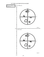
Страница 104: ...31 For NTSC mode For PAL mode DSC P1 DSC P1 FOR CAMERA COLOR REPRODUCTION ADJUSTMENT Take a copy of CAMERA COLOR REPRODUCTION FRAME with a clear sheet for use R Y B Y R B G MG YE CY R Y B Y R B G MG YE CY ...

Страница 105: ... 132 DSC P1 Sony Corporation Personal VIDEO Products Company 9 929 854 31 2000J0535 1 Printed in Japan 2000 10 Published by Safety Service Engineering Dept ...

Отзывы: